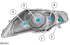
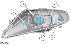
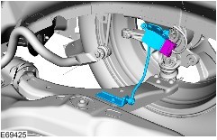
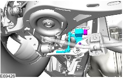
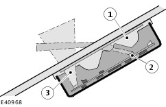
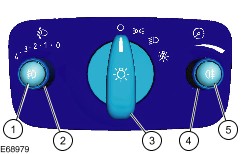
| Description and Operation Conventional Headlamps | Item | Lamp | Bulb | Current draw | Bulb color | | 1 | Side lamp | W5W | 5W | Clear | | 2 | Turn signal indicator | PY21W | 21W | Orange | | 3 | Dipped beam headlamps | H7 | 55W | Clear | | 4 | High beam headlamps | H1 | 55W | Clear | The headlamp units are primarily made of plastic and make use of free-form reflectors in order to optimize light distribution. The transparent plastic cover is made from polycarbonate, which is coated for protection against scratches and cracks. In the event of damage to the cover the entire headlamp unit needs to be replaced. The headlamp unit also houses the side lamp, the turn signal lamp and the main beam headlamp. The manual headlamp leveling control is activated via an electric motor which is controlled via a rotary regulator in the light switch. The headlamp leveling positioning motor cannot be replaced by itself. If necessary, it needs to be replaced together with the complete headlamp unit. For conventional headlamps, adapting the vehicle to conform to country-specific traffic situations (left/right-hand side traffic) during travel is accomplished by affixing punched adhesive strips to specific areas of the headlamp. All conventional headlamps use 12 V bulbs with a spiral-wound filament. Projector headlamps with dynamic adaptive front lighting and cornering lamps | Item | Lamp | Bulb | Current draw | Bulb color | | 1 | Side lamp | W5W | 5W | Clear | | 2 | Turn signal indicator | PY21W | 21W | Orange | | 3 | Dipped beam headlamps | H7 | 55W | Clear | | 4 | High beam headlamps | H1 | 55W | Clear | | 5 | Cornering lamps | H1 | 55W | Clear | Vehicles with projector headlamps are fitted with adaptive front lighting; in this case, the cornering lamps can be swiveled horizontally and are operated with a projector lens. The system is not compatible with automatic headlamp inclination and only works when the lights are switched on. When the dipped beam headlamps are in use only the projection headlamp is active. In full beam mode the full beam headlamps and the dipped beam headlamps are used. While cornering, the dipped beam projectors swivel toward the inside of the bend, whereby the maximum attainable correction angles are 9° for the projector on the outside of the bend and 14° for the projector on the inside of the bend. When reverse is engaged, the adaptive front lighting function is activated laterally reversed. When reverse gear is disengaged again and the vehicle moves at a speed above 3 km/h, the cornering lamps follow the relevant steering movements. During parking maneuvers at speeds of less than 3 km/h the cornering lamps are not activated in order to prevent dazzling oncoming traffic when the steering wheel is being turned from one side to the other. The adaptive front lighting actuator motors are stepper motors. The headlamp leveling positioning motor cannot be replaced by itself. If necessary, it needs to be replaced together with the complete headlamp unit. The headlamp leveling system motors are DC motors. The straight ahead position of the steering should be checked using the diagnostics unit prior to headlamp adjustment. For this purpose, the headlamp leveling system must be in the "0" position and the steering wheel in the "0" (+/- 3°) position. System error In the event of any system error(s) in the adaptive front lighting actuating motors the error message "Advanced Front Light Failure" is displayed on the driver information display in the instrument cluster. In the event of a headlamp leveling motor fault, both headlamps are moved to the central position by means of the adaptive front lighting actuator motors and they remain in this position. In the event of an adaptive front lighting actuator motor fault, the headlamp leveling motor moves the relevant headlamp to the lowest position where it remains. The intact headlamp is moved to the "0" position by the adaptive front lighting actuator motor. When touring, the adaptive front lighting headlamps are adapted to the various national traffic conditions (driving on the left/right) by switching over a lever inside the headlamp; the lever can be accessed by opening the rear headlamp cover. High intensity discharge headlamps with cornering lamps | Item | Lamp | Bulb | Current draw | Bulb color | | 1 | Side lamp | W5W | 5W | Clear | | 2 | Turn signal indicator | PY21W | 21W | Orange | | 3 | Dipped beam headlamps | D1S | 35W | Clear | | 4 | High beam headlamps | H1 | 55W | Clear | | 5 | Cornering lamps | H1 | 55W | Clear | WARNING:High voltages of up to 30 kV are present in the system. Ensure that the headlamp assembly electrical connector is disconnected if the headlamp assembly is removed. High intensity discharge headlamps are optionally available. A single Xenon gas discharge lamp in the center projector is used for both the dipped beam and main beam headlamps. In main beam mode the 15° aperture required for dipped beam operation is pushed out from the light beam by a positioning motor, as a result of which the full light beam of the gas discharge lamp becomes available. An additional reflector with a conventional filament bulb is available for main beam operation. This bulb is also switched when the headlamp flashers are used. The headlamp leveling positioning motor cannot be replaced by itself. If necessary, it needs to be replaced together with the complete headlamp unit. When touring, the high intensity discharge headlamps are adapted to the various national traffic conditions (driving on the left/right) by switching over a lever inside the headlamp; the lever can be accessed by opening the rear headlamp cover. Headlamp levelling An automatic headlamp leveling system is a legal requirement for vehicles with gas discharge headlamps. The automatic headlamp leveling system is a second-generation dynamic system which provides additional benefits for the driver in terms of improved illumination of the road due to improved control over the headlamp beam. In a static system, the vehicle is only considered as a stationary object, whereas a dynamic system also takes into account the dynamic changes to the inclination of the vehicle owing to load changes whilst driving. The system is designed to respond to changes in the inclination of the vehicle caused by the long-term effects of aerodynamic forces acting on the vehicle (e.g. due to continuous driving at high speeds). In order to prevent unnecessary changes in the height of the headlamp beam, the system filters out surface irregularities and any pitching of the vehicle under braking and acceleration. Front headlamp leveling sensor Rear headlamp leveling sensor The headlamp leveling sensors are Hall sensors, which transmit an analog signal to the control module. Accordingly, the system needs to be set up with the diagnostics unit after any components are replaced or any other repairs are carried out. Cornering lamps On vehicles with projection headlamps with dynamic adaptive front lighting or with gas discharge headlamps, an additional cornering light system is provided which is located in the inner part of the headlamp unit. The cornering lights are switched on depending on the vehicle speed (up to 80 km/h max.) in conjunction with the steering angle (approx. 30° with the vehicle stationary). As a requirement for this, either the dipped beam headlamps or the main beam headlamps need to be switched on. During cornering only the cornering light on the inside of the bend is switched on to improve illumination of the bend. Combined rain sensor/light sensor The combined rain sensor/light sensor is attached to the windshield, near the interior rear view mirror. The ambient light sensor determines the general light intensity. For this purpose, it detects the light over as wide an angle as possible, without taking the direction of incidence into account. The front light sensor determines the light intensity directly in front of the vehicle. Autolamps The low beams, side lamps, license plate lamps as well as the instrument cluster and instrument panel illumination are switched on automatically if all the following conditions are met: - Ignition switch in the "II" or "III" position
- Light switch in the "AUTO" position
- Detected ambient light conditions below a stored threshold value
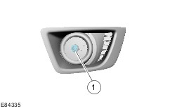
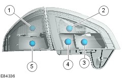
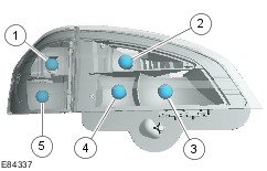
They are switched on or off by the GEM depending on the input signals of the combined rain sensor/light sensor. If both the ambient light sensor and the front light sensor simultaneously detect a sudden reduction in light intensity then algorithm-based calculations are performed to determine that the vehicle has entered a tunnel, multi-storey car park or a long underpass. In this type of case a request to switch on the exterior lights and the display lamps in the instrument cluster is transmitted to the GEM. If the vehicle enters into the shade thrown by a large truck, the two sensors will register different light intensities.. In this case, the algorithm-based calculation will not result in the lights being switched on. If the vehicle returns to brighter surroundings then the GEM gradually switches off the dipped beam headlamps, side lights, license plate lamps and the instrument cluster and dashboard lighting. Following a request from the light sensor, the GEM first switches off the dipped beam headlamps. After waiting approx. 6 seconds, it then switches off the side lights, the license plate lamps and the instrument cluster and dashboard lighting. Headlamp switch-off delay The headlamp switch-off delay utilizes the low beam together with the peripheral lights (if equipped) to illuminate the area surrounding the vehicle. The function is activated by operating the high beam lever when the ignition switch is in the "0" position. After the last door has been closed, the function remains active for a further 30 seconds and then switches off automatically. When a door or the tailgate is open, the switch-off time is extended to 180 seconds. After the last door has been closed, the switch-off time is reset to 30 seconds. The headlamp switch-off delay can be deactivated prematurely by operating the high beam lever again or by switching on the ignition. The switch-off time is adjusted to set values at the factory and cannot be re-programmed using the diagnostic unit. Front fog lamps. | Item | Lamp | Bulb | Current draw | Bulb color | | 1 | Fog lamp | HB4 | 55W | Clear | Rear lamps The rear lamps are a two-part design on all variants, the larger section of the rear lamp being located in the tailgate area. 4-door and 5-door | Item | Lamp | Bulb | Current draw | Bulb color | | 1 | Turn signal indicator | PY21W | 21W | Orange | | 2 | Reversing Lamp | P21W | 21W | Clear | | 3 | Rear fog lamp | P21W | 21W | Clear | | 4 | Side lamp | W5W | 5W | Clear | | 5 | Stoplamp/side lamp | P21/5W | 21/5W | Clear | Wagon | Item | Lamp | Bulb | Current draw | Bulb color | | 1 | Turn signal indicator | PY21W | 21W | Orange | | 2 | Reversing Lamp | P21W | 21W | Clear | | 3 | Rear fog lamp | P21W | 21W | Clear | | 4 | Side lamp | W5W | 5W | Clear | | 5 | Stoplamp/side lamp | P21/5W | 21/5W | Clear | Stoplamp On the wagon, the additional high-mounted stoplamp is mounted in the middle of the tailgate above the rear window and also incorporates the washer nozzle for the rear window. A W16W glass base bulb is used. On the 4 and 5-door versions, the additional high-mounted stoplamp is installed in the tailgate. A W16W glass base bulb is used. The stoplamps are switched on via the stoplamp switch on the brake pedal as soon as the brake pedal is actuated. Parking lamps The parking lamps are switched on for the relevant side of the vehicle via the turn signal lever when the ignition switch is in position "0". In addition, there is also a parking lights function on the light switch which can be used to switch on all side lights. Light switch 2 - Headlamp leveling (only on vehicles with manual operation) 3 - Parking lamps, dipped beam headlamps, automatic headlamps (optional) The light switch has been modified and now includes electronic controls. It is connected to the GEM via a control module subnetwork (LIN) bus. After switching the ignition off and back on again the front fog lamps and the rear fog lamp are deactivated. They then need to be switched back on again if they are required. If the ignition lock is in position "0" for more than 30 minutes then the front fog lamps, rear fog lamp and the main beam headlamps are deactivated if they were previously activated. Lamp failure detection Failure of the following lighting components is indicated to the driver via the display in the instrument panel: - Dipped beam headlamps
- Stoplamp
- Rear fog lamp
- Trailer turn signal lamp (only in trailer mode; controlled by the trailer module)
- Trailer stoplamp (only in trailer mode; controlled by the trailer module)
The indicator lamp in the instrument cluster flashes at twice the normal frequency to indicate failure of the turn signal lamp. Malfunction of the bulb control module on vehicles with adaptive front lighting is indicated via the display in the instrument cluster. Emergency function A monitoring function within the GEM is sent a control signal at regular intervals. If for example the battery voltage drops below a voltage of approx. 7.5 Volt then the control signal is not sent and the GEM goes into emergency running mode after a specified time. In this case the dipped beam headlamps and the side lights are switched on permanently depending on the position of the light switch. |