| Diagnosis and Testing Refer to Wiring Diagrams Section 501-16, for schematic and connector information. Special Tool(s) | | Terminal Probe Kit 29-011A | General Equipment IDS diagnosis system 73III Automatic Meter Inspection and Verification NOTE:The generic electronic module (GEM) is part of the central junction box (CJB). NOTE:If the generic electronic module (GEM) is changed, the new one must be configured. For this purpose, the vehicle-specific data are read out of the module to be replaced using the diagnostic tester and transferred to the new module. REFER to: Modul-Konfiguration (418-01 Modul-Konfiguration, General Procedures), Zentralelektrikmodul (GEM) (419-10 Multifunktionsmodule, Diagnosis and Testing). NOTE:Before reading out the vehicle-specific data make sure that all electrical connections in the vehicle are reconnected so that the module and the diagnostic unit can communicate correctly. NOTE:Ensure correct engagement of the wiring harness connectors. - Verify the customer concern.
- Visually inspect for obvious signs of mechanical or electrical damage.
Visual Inspection Chart | Mechanical | Electrical systems | - Wiper blade(s)
- Wiper arm pivot shaft
- Washer reservoir
- Hose(s)
- Washer nozzles
- Check the wiper blades for residue-free wiping in the vicinity of the rain sensor.
- Check the adhesive pad between the rain sensor and the windshield for trapped air.
- Clean wax residues from the windshield in the vicinity of the rain sensor.
- Check the windshield for damage/cracks in the vicinity of the rain sensor.
- Check that the rain sensor retaining frame is correctly attached to the windshield.
| - Fuse(s)
- Connector
- Wiring loom
- Washer pump
- Headlamp washer pump
- Front/rear window wiper motor
- Wash/wipe switch
- Central junction box (CJB):
- Rear Junction Box (RJB)
- Battery junction box (BJB)
| - RECTIFY any obvious causes for a concern found during the visual inspection before performing any further tests.
- If the concern is not visually evident, PERFORM a fault diagnosis on the generic electronic module (GEM) using the diagnostic unit and RECTIFY any displayed faults in accordance with the displayed fault description. CHECK operation of system.
- On a vehicle without stored fault(s), continue according to the Symptom Chart and the corresponding symptom.
- After testing or rectifying the fault and after completion of operations, READ OUT the fault memories of all vehicle modules and DELETE any stored faults. READ OUT all fault memories again after a road test.
Trouble Code Table - Generic Electronic Module (GEM) | Self-test code | Description | Action | | 909512 | Front windshield wiper relay circuit (on/off) faulty (short to voltage) | GO to Pinpoint Test A. | | 909514 | Front windshield wiper relay circuit (on/off) faulty (short to ground or open circuit) | Short to ground: GO to Pinpoint Test D. | | Open circuit: GO to Pinpoint Test A. | | 909612 | Front windshield wiper relay circuit (fast/slow) faulty (short to voltage) | Slow wipe speed inoperative: GO to Pinpoint Test B. | | Fast wipe speed inoperative: GO to Pinpoint Test C. | | 909614 | Front windshield wiper relay circuit (fast/slow) faulty (short to ground or open circuit) | Short to ground: GO to Pinpoint Test B. | | Open circuit: GO to Pinpoint Test C. | | 90AD04 | Internal circuit of rain sensor/light sensor faulty | GO to Pinpoint Test E. | | 90AD09 | Rain sensor/light sensor, component fault | GO to Pinpoint Test E. | | 9C8212 | Fault in circuit of headlamp washer system relay (short to voltage) | GO to Pinpoint Test J. | | 9C8214 | Fault in circuit of headlamp washer system relay (short to ground or open circuit) | Short to ground: GO to Pinpoint Test K. | | Open circuit: GO to Pinpoint Test J. | Symptom chart | Symptom | Possible Sources | Action | | After the ignition is switched on, the front windshield wipers run continuously at slow wipe speed. No communication between the steering wheel module (SWM) and the generic electronic module (GEM). | * Fuse * Circuit(s) * Central junction box (CJB) / generic electronic module (GEM) * Steering wheel module (SWM) | * REFER to: Kommunikations-Netzwerk (418-00 Modul-Kommunikations-Netzwerk, Diagnosis and Testing). | | Wipers inoperative. | * Fuse(s) * Circuit(s) * Central junction box (CJB) / generic electronic module (GEM) * Windshield wiper motor * Rear window wiper motor * Front windshield wiper relay (on/off) * Front windshield wiper relay (fast/slow) * Rear wiper relay | * | | Slow wipe speed inoperative (fast wipe speed OK). | * Circuit(s) * Front windshield wiper relay (fast/slow) * Wash/wipe switch | * | | Fast wipe speed inoperative (slow wipe speed OK). | * Circuit(s) * Front windshield wiper relay (fast/slow) * Wash/wipe switch | * | | Front windshield wipers operating all the time. | * Circuit(s) * Windshield wiper motor * Front windshield wiper relay (on/off) * Front windshield wiper relay (fast/slow) * Rain Sensor * Wash/wipe switch | * | | Front wiper intermittent mode or automatic mode is inoperative. | * Fuse(s) * Circuit(s) * Wash/wipe switch * Central junction box (CJB) / generic electronic module (GEM) * Steering wheel module (SWM) * Rain Sensor | * | | Front intermittent wipe function operating all the time. | * Wash/wipe switch | * CHECK the wash/wipe system switch according to the component check at the end of this section. CHECK operation of system. If the concern persists, check the steering wheel module (SWM) using the diagnostic unit and RENEW if necessary. CHECK operation of system. | | The front windshield wiper does not return to the park position after being switched off. | * Circuit * Front windshield wiper motor | * | | Rear window wiper operating all the time. | * Circuit(s) * Wash/wipe switch * Rear window wiper motor * Rear wiper relay * Central junction box (CJB) / generic electronic module (GEM) | * | | The rear window wiper does not return to the park position after being switched off. | * Circuit(s) * Rear window wiper motor | * | | Washer pump inoperative (wiper function OK). | * Fuse(s) * Circuit(s) * Wash/wipe switch * Washer pump * Central junction box (CJB) / generic electronic module (GEM) | * | | The headlamp cleaning system is inoperative. | * Fuse(s) * Circuit(s) * Headlamp washer system relay * Headlamp washer pump * Central junction box (CJB) / generic electronic module (GEM) | * | | The headlamp washer system is operating all the time. | * Circuit(s) * Headlamp washer system relay * Central junction box (CJB) / generic electronic module (GEM) | * | | The nozzle heating is inoperative. | * Fuse(s) * Circuit(s) * Left/right-hand nozzle | * | Pinpoint Tests | PINPOINT TEST A : THE WINDSHIELD WIPERS ARE INOPERATIVE (ALL SPEEDS) | | TEST CONDITIONS | DETAILS/RESULTS/ACTIONS | | A1: DETERMINE THE CAUSE OF THE FAULT | | | 1 Ignition switch in position II. | | | 2 TURN ON the front and the rear wiper. | | | Are only the windshield wipers inoperative? Yes The windshield wipers are inoperative: GO to A2. No The rear window wipers are inoperative: GO to A13. | | A2: CHECK FUSE F22 | | | 1 Ignition switch in position 0. | | | 2 CHECK Fuse F22 (BJB). | | | Is fuse OK? Yes No RENEW fuse F22 (30 A). If the fuse blows again, LOCATE and REPAIR the short circuit by using the wiring diagrams. CHECK operation of system. | | A3: CHECK THE VOLTAGE AT FUSE F22 | | | 1 Connect Fuse F22 (BJB). | | | 2 Measure the voltage between fuse F22 (30 A) and ground. | | | Does the meter display battery voltage? Yes No REPAIR the voltage supply to fuse F22 with the aid of the Wiring Diagrams. CHECK operation of system. | | A4: CHECK THE VOLTAGE AT THE FRONT WINDSHIELD WIPER RELAY (ON/OFF) | | | 1 Disconnect Front windshield wiper relay (on/off) from socket R11 (BJB) . | | | 2 Measure the voltage between the front windshield wiper relay (on/off), socket R11, pin 1, circuit SBB22G (BN/RD), wiring harness side and ground. | | | 3 Measure the voltage between the front windshield wiper relay (on/off), socket R11, pin 5, circuit SBB22D (BN/RD), wiring harness side and ground. | | | Is battery voltage measured in both cases? Yes No If both measurements show no voltage:LOCATE and REPAIR the break in circuit SBB22E (BN/RD) between fuse F22 and soldered connection SP738 with the aid of the Wiring Diagrams. CHECK operation of system. | | A5: CHECK THE FRONT WINDSHIELD WIPER MOTOR CIRCUIT | | | 1 Using a fused test cable (30 A) at the front windshield wiper relay (on/off), bridge between socket R11, pin 3, circuit A_CRW03A (VT/WH) and pin 5, circuit SBB22D (BN/RD), wiring harness side. | | | 2 CHECK the operation of the front windshield wipers. | | | Is the front wiper on? Yes No | | A6: CHECK THE FRONT WINDSHIELD WIPER RELAY (ON/OFF) | | | 1 CHECK the front windshield wiper relay (on/off) according to the component tests at the end of this subsection. | | | Is the relay OK? Yes No RENEW the front windshield wiper relay (on/off). CHECK operation of system. | | A7: CHECK THE VOLTAGE AT THE FRONT WINDSHIELD WIPER RELAY (FAST/SLOW) | | | 1 Connect Front windshield wiper relay (on/off) to socket R11 (BJB) . | | | 2 Disconnect Front windshield wiper relay (fast/slow) from socket R8. | | | 3 Ignition switch in position II. | | | 4 Switch on the front windshield wipers. | | | 5 Measure the voltage between the front windscreen wiper relay (fast/slow), socket R8, pin 3, circuit A_CRW03A (VT/WH), wiring harness side and ground. | | | Does the meter display battery voltage? Yes No LOCATE and REPAIR break in circuit A_CRW03A (VT/WH) between the front windshield wiper relay (on/off) and the front windshield wiper relay (fast/slow) using the wiring diagrams. CHECK operation of system. | | A8: CHECK THE FRONT WINDSHIELD WIPER MOTOR CIRCUIT | | | 1 Ignition switch in position 0. | | | 2 Using a fused test cable (30 A) at the front windshield wiper relay (fast/slow), bridge between socket R8, pin 3, circuit A_CRW03A (VT/WH) and pin 4, circuit CRW16A (GN/BN), wiring harness side. | | | 3 Ignition switch in position II. | | | 4 CHECK the operation of the front windshield wipers. | | | Does the front windshield wiper move at normal speed? Yes RENEW the front windshield wiper relay (fast/slow). CHECK operation of system. No | | A9: CHECK THE GROUND CONNECTION OF THE FRONT WINDSHIELD WIPER MOTOR | | | 1 Ignition switch in position 0. | | | 2 Disconnect Connector C1RW01-A from front windshield wiper motor. | | | 3 Measure the resistance between the front windshield wiper motor, connector C1RW01-A, pin 4, circuit GD131L (BK/GY), wiring harness side and ground. | | | Is a resistance of less than 2 ohms registered? Yes RENEW the front wiper motor CHECK operation of system. No LOCATE and REPAIR the break in circuit GD131L (BK/GY) between front windshield wiper motor and splice SP373 using the wiring diagrams. CHECK operation of system. | | A10: CHECK CIRCUIT BETWEEN GENERIC ELECTRONIC MODULE (GEM) AND BATTERY JUNCTION BOX (BJB) FOR OPEN CIRCUIT | | | 1 Disconnect Front windshield wiper relay (on/off) from socket R11 (BJB) . | | | 2 Disconnect Connector C1BP02-A from the generic electronic module (GEM). | | | 3 Measure the resistance between GEM, connector C1BP02-A, pin 43, circuit CRW01A (WH), wiring harness side and BJB, socket R11, pin 2, circuit CRW01A (WH), wiring harness side. | | | Is a resistance of less than 2 ohms registered? Yes No LOCATE and RECTIFY the break in circuit CRW01A (WH) between GEM and BJB with the aid of the Wiring Diagrams. CHECK operation of system. | | A11: CHECK CIRCUIT BETWEEN GENERIC ELECTRONIC MODULE (GEM) AND BATTERY JUNCTION BOX (BJB) FOR SHORT TO VOLTAGE | | | 1 Ignition switch in position II. | | | 2 Measure the voltage between the BJB, socket R11, pin 2, circuit CRW01A (WH), wiring harness side and ground. | | | Is a voltage measured? Yes LOCATE and RECTIFY the short to voltage in circuit CRW01A (WH) between GEM and BJB with the aid of the Wiring Diagrams. CHECK operation of system. No | | A12: CHECK THE WASH/WIPE SWITCH | | | 1 Ignition switch in position 0. | | | 2 CHECK the wash/wipe system switch according to the component check at the end of this section. - Wash/wipe system switch: perform the measurement at pins 3, 4, 5, 6, 7 and 8.
| | | Is the wash/wipe switch OK? Yes CHECK the steering wheel module (SWM) using the diagnostic unit and RENEW if necessary. CHECK operation of system. If the concern persists, CHECK the GEM with the diagnostic unit and RENEW if necessary. CHECK operation of system. No RENEW the wash/wipe switch. CHECK operation of system. | | A13: CHECK FUSE F45 | | | 1 Ignition switch in position 0. | | | 2 CHECK fuse F45 (BJB). | | | Is fuse OK? Yes No RENEW fuse F45 (15 A) and CHECK the operation of the system. If the fuse blows again, LOCATE and REPAIR the short circuit by using the wiring diagrams. CHECK operation of system. | | A14: CHECK THE VOLTAGE AT FUSE F45 | | | 1 Connect fuse F45 (BJB). | | | 2 Ignition switch in position II. | | | 3 Measure the voltage between fuse F45 (15 A) and ground. | | | Does the meter display battery voltage? Yes No REPAIR the voltage supply to fuse F45 using the Wiring Diagrams. CHECK operation of system. | | A15: CHECK THE VOLTAGE AT THE REAR WINDOW WIPER RELAY | | | 1 Ignition switch in position 0. | | | 2 Disconnect Rear window wiper relay from socket RA2 (RJB). | | | 3 Ignition switch in position II. | | | 4 Measure the voltage between the rear window wiper relay, socket RA2, pin 1, circuit SBR07C (WH/RD), wiring harness side and ground. | | | 5 Measure the voltage between the rear window wiper relay, socket RA2, pin 5, circuit CBB45D (YE), wiring harness side and ground. | | | Is battery voltage measured in both cases? Yes No - No battery voltage measured at pin 1:LOCATE and REPAIR the break in circuit SBR07C (WH/RD) between splice SP425 and rear window wiper relay with the aid of the Wiring Diagrams. CHECK operation of system. - No battery voltage measured at pin 5:LOCATE and RECTIFY the break in circuit CBB45D (YE) between soldered connection SP903 and the RJB using the Wiring Diagrams. CHECK operation of system. | | A16: CHECK THE CIRCUIT OF THE REAR WINDOW WIPER | | | 1 Ignition switch in position 0. | | | 2 Using a fused test cable (15 A) at the rear window wiper relay, connect socket RA2, pin 3, circuit CRW05B (BU), and pin 5, circuit CBB45D (YE), wiring harness side. | | | 3 Ignition switch in position II. | | | 4 CHECK the operation of the rear window wiper. | | | Is the rear wiper operating? Yes No | | A17: CHECK THE REAR WINDOW WIPER RELAY | | | 1 Ignition switch in position 0. | | | 2 CHECK the rear window wiper relay according to the component tests at the end of this subsection. | | | Is the relay OK? Yes No RENEW the rear window wiper relay. CHECK operation of system. | | A18: CHECK THE VOLTAGE AT THE REAR WINDOW WIPER MOTOR (PIN 2) | | | 1 Ignition switch in position 0. | | | 2 Connect Rear window wiper relay to socket RA2 (RJB). | | | 3 Disconnect Connector C4RW02 from rear window wiper motor . | | | 4 Ignition switch in position II. | | | 5 TURN ON the rear window wiper. | | | NOTE:Minimum measuring period 30 seconds. 6 Measure the voltage between the rear window wiper motor, connector C4RW02, pin 2, circuit CRW05A (BU), wiring harness side and ground. | | | Is battery voltage measured every 10 seconds? Yes No LOCATE AND REPAIR break in circuit between RJB and rear window wiper motor using the wiring diagrams. CHECK operation of system. | | A19: CHECK THE VOLTAGE AT THE REAR WINDOW WIPER MOTOR (PIN 1) | | | 1 Measure the voltage between the rear window wiper motor, connector C4RW02, pin 1, circuit CBB45F (BK), wiring harness side and ground. | | | Does the meter display battery voltage? Yes No LOCATE and REPAIR open circuit between rear window wiper motor and splice SP903 using the wiring diagrams. CHECK operation of system. | | A20: CHECK THE GROUND CONNECTION OF THE REAR WINDOW WIPER MOTOR | | | 1 Ignition switch in position 0. | | | 2 Measure the resistance between the rear window wiper motor, connector C4RW02, pin 3, circuit GD150S (BK/WH), wiring harness side and ground. | | | Is a resistance of less than 2 ohms registered? Yes RENEW the rear window wiper motor. CHECK operation of system. No LOCATE and REPAIR open circuit between rear window wiper motor and splice SP534 using the wiring diagrams. CHECK operation of system. | | A21: CHECK FOR BREAK IN CIRCUIT BETWEEN THE GENERIC ELECTRONIC MODULE (GEM) AND THE REAR JUNCTION BOX (RJB). | | | 1 Disconnect Connector C1BP02-B from the GEM. | | | 2 Measure the resistance between the GEM, connector C1BP02-B, pin 42, circuit CRW02A (GY/BU), wiring harness side and RJB, socket RA2, pin 2, circuit CRW02A (GY/BU), wiring harness side. | | | Is a resistance of less than 2 ohms registered? Yes No LOCATE and RECTIFY the break in the circuit between the GEM and the RJB with the aid of the Wiring Diagrams. CHECK operation of system. | | A22: CHECK CIRCUIT BETWEEN THE GENERIC ELECTRONIC MODULE (GEM) AND THE REAR JUNCTION BOX (RJB) FOR SHORT CIRCUIT TO BATTERY VOLTAGE | | | 1 Ignition switch in position II. | | | 2 Measure the voltage between the GEM, connector C1BP02-B, pin 42, circuit CRW02A (GY/BU), wiring harness side and ground. | | | Does the meter display battery voltage? Yes LOCATE and RECTIFY the short to battery voltage in circuit CRW02A (GY/BU) between the GEM and the RJB with the aid of the Wiring Diagrams. CHECK operation of system. No | | A23: CHECK THE WASH/WIPE SWITCH | | | 1 Ignition switch in position 0. | | | 2 CHECK the wash/wipe system switch according to the component check at the end of this section. - Wash/wipe system switch: Carry out measurement at pins 2 and 6.
| | | Is the wash/wipe switch OK? Yes CHECK the steering wheel module (SWM) using the diagnostic unit and RENEW if necessary. CHECK operation of system. If the concern persists, CHECK the GEM with the diagnostic unit and RENEW if necessary. CHECK operation of system. No RENEW the wash/wipe switch. CHECK operation of system. | | PINPOINT TEST B : SLOW WIPE SPEED INOPERATIVE (FAST WIPE SPEED OK) | | TEST CONDITIONS | DETAILS/RESULTS/ACTIONS | | B1: CHECK THE CIRCUIT OF THE FRONT WINDSHIELD WIPER MOTOR (SLOW SPEED) | | | 1 Ignition switch in position 0. | | | 2 Disconnect Front windshield wiper relay (fast/slow) from socket R8 (BJB). | | | 3 Using a fused test cable (30 A) at the front windshield wiper relay (fast/slow), bridge between socket R8, pin 3, circuit A_CRW03A (VT/WH) and pin 4, circuit CRW16A (GY/BN), wiring harness side. | | | 4 Ignition switch in position II. | | | 5 Set the wash/wipe system switch to position II (slow wipe). | | | Does the windshield wiper operate at the selected speed? Yes No | | B2: CHECK THE FRONT WINDSHIELD WIPER RELAY (FAST/SLOW) | | | 1 Ignition switch in position 0. | | | 2 CHECK the front windshield wiper relay (fast/slow) according to the component tests at the end of this subsection. | | | Is the relay OK? Yes No RENEW the front windshield wiper relay (fast/slow). CHECK operation of system. | | B3: CHECK FOR OPEN CIRCUIT BETWEEN THE BATTERY JUNCTION BOX (BJB) AND THE FRONT WINDSHIELD WIPER MOTOR | | | 1 Ignition switch in position 0. | | | 2 Disconnect Front windshield wiper relay (fast/slow) from socket R8 (BJB). | | | 3 Measure the resistance between the BJB, socket R8, pin 4, circuit CRW16A (GY/BN), wiring harness side and the front windshield wiper motor, connector C1RW01-A, pin 2, circuit CRW16A (GY/BN), wiring harness side. | | | Is a resistance of less than 2 ohms registered? Yes RENEW the front windshield wiper motor. CHECK operation of system. No LOCATE and REPAIR the break in circuit CRW16A (GY/BN) between the BJB and the front windshield wiper motor with the aid of the Wiring Diagrams. CHECK operation of system. | | B4: CHECK THE WASH/WIPE SWITCH | | | 1 Ignition switch in position 0. | | | 2 CHECK the wash/wipe system switch according to the component check at the end of this section. - Wash/wipe system switch: Measure at pins 3, 7 and 8.
| | | Is the wash/wipe switch OK? Yes CHECK the steering wheel module (SWM) using the diagnostic unit and RENEW if necessary. CHECK operation of system. If the concern persists, CHECK the GEM with the diagnostic unit and RENEW if necessary. CHECK operation of system. No RENEW the wash/wipe switch. CHECK operation of system. | | PINPOINT TEST C : FAST WIPE SPEED INOPERATIVE (SLOW WIPE SPEED OK) | | TEST CONDITIONS | DETAILS/RESULTS/ACTIONS | | C1: CHECK THE VOLTAGE AT THE FRONT WINDSHIELD WIPER RELAY (FAST/SLOW) | | | 1 Ignition switch in position 0. | | | 2 Disconnect Front windshield wiper relay (fast/slow) from socket R8 (BJB). | | | 3 Measure the voltage between the front windshield wiper relay (slow/fast), socket R8, pin 1, circuit SBB22F (BN/RD), wiring harness side and ground. | | | Does the meter display battery voltage? Yes No LOCATE and REPAIR the break in circuit SBB22F (BN/RD) between the front windshield wiper relay (slow/fast) and soldered connection SP738 with the aid of the Wiring Diagrams. CHECK operation of system. | | C2: CHECK THE CIRCUIT OF THE FRONT WINDSHIELD WIPER MOTOR (FAST SPEED) | | | 1 Ignition switch in position 0. | | | 2 Using a fused test cable (30 A) at the front windshield wiper relay (fast/slow), bridge between socket R8, pin 3, circuit A_CRW03A (VT/WH) and pin 5, circuit CRW03A (VT/WH), wiring harness side. | | | 3 Ignition switch in position II. | | | 4 Set the wash/wipe system switch to position III (fast wipe). | | | Does the front windshield wiper operate at the selected speed? Yes No | | C3: CHECK FOR OPEN CIRCUIT BETWEEN THE BATTERY JUNCTION BOX (BJB) AND THE FRONT WINDSHIELD WIPER MOTOR | | | 1 Ignition switch in position 0. | | | 2 Measure the resistance between the BJB, socket R8, pin 5, circuit CRW03A (VT/WH), wiring harness side and the front windshield wiper motor, connector C1RW01-A, pin 1, circuit CRW03A (VT/WH), wiring harness side. | | | Is a resistance of less than 2 ohms registered? Yes RENEW the front windshield wiper motor. CHECK operation of system. No LOCATE and REPAIR the break in circuit CRW03A (VT/WH) between the BJB and the front windshield wiper motor with the aid of the Wiring Diagrams. CHECK operation of system. | | C4: CHECK THE FRONT WINDSHIELD WIPER RELAY (FAST/SLOW) | | | 1 Ignition switch in position 0. | | | 2 CHECK the front windshield wiper relay (fast/slow) according to the component tests at the end of this subsection. | | | Is the relay OK? Yes No RENEW the front windshield wiper relay (fast/slow). CHECK operation of system. | | C5: CHECK CIRCUIT BETWEEN BATTERY JUNCTION BOX (BJB) AND GENERIC ELECTRONIC MODULE (GEM) FOR OPEN CIRCUIT | | | 1 Ignition switch in position 0. | | | 2 Disconnect Connector C1BP02-A from the generic electronic module (GEM). | | | 3 Measure the resistance between the BJB, socket R8, pin 2, circuit CRW15A (BN/WH), wiring harness side and the GEM, connector C1BP02-A, pin 41, circuit CRW15A (BN/WH), wiring harness side. | | | Is a resistance of less than 2 ohms registered? Yes No LOCATE and REPAIR the break in circuit CRW15A (BN/WH) between the BJB and the front windshield wiper motor with the aid of the Wiring Diagrams. CHECK operation of system. | | C6: CHECK CIRCUIT BETWEEN BATTERY JUNCTION BOX (BJB) AND GENERIC ELECTRONIC MODULE (GEM) FOR SHORT TO VOLTAGE | | | 1 Ignition switch in position II. | | | 2 Measure the voltage between the BJB, socket R8, pin 2, circuit CRW15A (BN/WH), wiring harness side and ground. | | | Is a voltage measured? Yes LOCATE and RECTIFY the short to voltage in circuit CRW15A (BN/WH) between BJB and GEM with the aid of the Wiring Diagrams. CHECK operation of system. No | | C7: CHECK THE WASH/WIPE SWITCH | | | 1 Ignition switch in position 0. | | | 2 CHECK the wash/wipe system switch according to the component check at the end of this section. - Wash/wipe system switch: Measure at pins 3 and 8.
| | | Is the wash/wipe switch OK? Yes CHECK the steering wheel module (SWM) using the diagnostic unit and RENEW if necessary. CHECK operation of system. If the concern persists, CHECK the GEM with the diagnostic unit and RENEW if necessary. CHECK operation of system. No RENEW the wash/wipe switch. CHECK operation of system. | | PINPOINT TEST D : WINDSCREEN WIPER RUNS CONTINUOUSLY | | TEST CONDITIONS | DETAILS/RESULTS/ACTIONS | | D1: CHECK THE EQUIPMENT LEVEL OF THE VEHICLE | | | 1 Check the equipment level of the vehicle | | | Is the vehicle equipped with a rain sensor and does the wash/wipe system switch show position I (AUTO)? Yes No | | D2: CHECK THE RAIN SENSOR | | | 1 Ignition switch in position 0. | | | 2 Disconnect Connector C9RW06 from rain sensor. | | | 3 Ignition switch in position II. | | | 4 Set the wash/wipe system switch to position I (AUTO). | | | Does the front windshield wiper motor operate continuously? Yes No RENEW the rain sensor. CHECK operation of system. | | D3: CHECK THE FRONT WINDSHIELD WIPER RELAY (ON/OFF) | | | 1 Ignition switch in position 0. | | | 2 Disconnect Front windshield wiper relay (on/off) from socket R11 (BJB) . | | | 3 Ignition switch in position II. | | | Is the front wiper motor working? Yes No | | D4: CHECK THE VOLTAGE OF THE FRONT WINDSHIELD WIPER RELAY (FAST/SLOW) | | | 1 Ignition switch in position 0. | | | 2 Disconnect Front windshield wiper relay (fast/slow) from socket R8. | | | 3 Ignition switch in position II. | | | 4 Measure the voltage between the front windshield wiper relay (fast/slow), socket R8, pin 3, circuit A_CRW03A (VT/WH), wiring harness side and ground. | | | Is a voltage measured? Yes LOCATE and REPAIR short to voltage in circuit A_CRW03A (VT/WH) between the front windshield wiper relay (on/off) and the front windshield wiper relay (fast/slow) using the wiring diagrams. CHECK operation of system. No - Windshield wiper operates slowly:LOCATE and RECTIFY the short to voltage in circuit CRW16A (GY/BN) between BJB and the front windshield wiper motor with the aid of the Wiring Diagrams. CHECK operation of system. - Windshield wiper operates quickly:LOCATE and RECTIFY the short to voltage in circuit CRW03A (VT/WH) between BJB and the front windshield wiper motor with the aid of the Wiring Diagrams. CHECK operation of system. | | D5: CHECK THE FRONT WINDSHIELD WIPER RELAY (ON/OFF) | | | 1 Ignition switch in position 0. | | | 2 CHECK the front windshield wiper relay (on/off) according to the component tests at the end of this subsection. | | | Is the windshield wiper relay (on/off) OK? Yes No RENEW the front windshield wiper relay (on/off). CHECK operation of system. | | D6: CHECK FOR A SHORT IN THE CIRCUIT BETWEEN THE BATTERY JUNCTION BOX (BJB) AND THE GENERIC ELECTRONIC MODULE (GEM) | | | 1 Disconnect Connector C1BP02-A from the generic electronic module (GEM). | | | 2 Measure the resistance between the BJB, socket R11, pin 2, circuit CRW01A (WH), wiring harness side and ground. | | | Is a resistance of more than 10,000 ohms measured? Yes No LOCATE and RECTIFY the short in circuit CRW01A (WH) between GEM and BJB with the aid of the Wiring Diagrams. CHECK operation of system. | | D7: CHECK THE WASH/WIPE SWITCH | | | 1 CHECK the wash/wipe system switch according to the component check at the end of this section. - Check the wash/wipe system switch at pins 3, 6, 7 and 8.
| | | Is the wash/wipe switch OK? Yes CHECK the steering wheel module (SWM) using the diagnostic unit and RENEW if necessary. CHECK operation of system. If the concern persists, CHECK the GEM with the diagnostic unit and RENEW if necessary. CHECK operation of system. No RENEW the wash/wipe switch. CHECK operation of system. | | PINPOINT TEST E : FRONT WIPER INTERMITTENT MODE OR AUTOMATIC MODE IS INOPERATIVE. | | TEST CONDITIONS | DETAILS/RESULTS/ACTIONS | | E1: CHECK THE EQUIPMENT LEVEL OF THE VEHICLE | | | 1 Check the equipment level of the vehicle | | | Is the vehicle equipped with a rain sensor? Yes No | | E2: CHECK THE WASH/WIPE SWITCH | | | 1 Ignition switch in position 0. | | | 2 CHECK the wash/wipe system switch according to the component check at the end of this section. - Check the wash/wipe system switch at pins 3 and 7.
| | | Is the wash/wipe switch OK? Yes CHECK the steering wheel module (SWM) using the diagnostic unit and RENEW if necessary. CHECK operation of system.If the concern persists, CHECK the GEM with the diagnostic unit and RENEW if necessary. CHECK operation of system. No RENEW the wash/wipe switch. CHECK operation of system. | | E3: DETERMINE THE CONDITION UNDER WHICH THE FAULT OCCURS | | | 1 Ignition switch in position II. | | | 2 Set the wash/wipe system switch to position I (AUTO). | | | 3 Set the adjusting ring on the wash/wipe system switch to the wide symbol (high sensitivity). Wet the windshield several times with a small amount of water in the vicinity of the rain sensor, in order to check whether the front wiper motor runs at slow wipe speed. | | | 4 Set the adjusting ring on the wash/wipe system switch to the narrow symbol (low sensitivity). Wet the windshield several times with a large amount of water in the vicinity of the rain sensor, in order to check whether the front wiper motor runs at fast wipe speed. | | | 5 CHECK the operation of the front windshield wiper. | | | Does the front windshield wiper operate each time at the selected speed? Yes But the sensitivity of the auto function cannot be ADJUSTED: GO to E4. No Rain sensor check.
REFER to: Kommunikations-Netzwerk (418-00, Diagnosis and Testing).
| | E4: CHECK THE WASH/WIPE SWITCH | | | 1 Ignition switch in position 0. | | | 2 CHECK the wash/wipe system switch according to the component check at the end of this section. - Check the wash/wipe system switch at pins 4, 5, 6 and 7.
| | | Is the wash/wipe switch OK? Yes CHECK the steering wheel module (SWM) using the diagnostic unit and RENEW if necessary. CHECK operation of system.If the concern persists, CHECK the GEM with the diagnostic unit and RENEW if necessary. CHECK operation of system. No RENEW the wash/wipe switch. CHECK operation of system. | | PINPOINT TEST F : THE WINDSHIELD WIPER DOES NOT RETURN TO THE PARK POSITION AFTER BEING SWITCHED OFF | | TEST CONDITIONS | DETAILS/RESULTS/ACTIONS | | F1: CHECK CIRCUIT BETWEEN CENTRAL JUNCTION BOX (CJB) AND FRONT WINDSHIELD WIPER MOTOR FOR SHORT TO GROUND | | | 1 Ignition switch in position 0. | | | 2 Disconnect Connector C1RW01-A from front windshield wiper motor. | | | 3 Measure the resistance between the front windshield wiper motor, connector C1RW01-A, pin 3, circuit CRW09A (BN/BU), wiring harness side and ground. | | | Is a resistance of more than 10,000 ohms measured? Yes RENEW the front wiper motor CHECK operation of system. No LOCATE and RECTIFY the short to ground in circuit CRW09A (BN/BU) between the GEM and the front windshield wiper motor with the aid of the Wiring Diagrams. CHECK operation of system. | | PINPOINT TEST G : THE REAR WINDOW WIPER RUNS CONTINUOUSLY | | TEST CONDITIONS | DETAILS/RESULTS/ACTIONS | | G1: CHECK THE REAR WINDOW WIPER RELAY | | | 1 Ignition switch in position 0. | | | 2 Disconnect Rear window wiper relay from socket RA2 (RJB). | | | 3 Ignition switch in position II. | | | Is the rear window wiper motor operating continuously? Yes No | | G2: CHECK THE CIRCUIT BETWEEN THE REAR WINDOW WIPER MOTOR AND THE REAR JUNCTION BOX (RJB) FOR SHORT TO VOLTAGE | | | 1 Ignition switch in position II. | | | 2 Measure the voltage between the rear window wiper relay, socket RA2, pin 3, circuit CRW05B (BU), wiring harness side and ground. | | | Is a voltage measured? Yes LOCATE and RECTIFY the short to battery voltage in the circuit between the RJB and the rear window wiper motor using the Wiring Diagrams. CHECK operation of system. No RENEW the rear window wiper motor. CHECK operation of system. | | G3: CHECK THE REAR WINDOW WIPER RELAY | | | 1 Ignition switch in position 0. | | | 2 CHECK the rear window wiper relay according to the component tests at the end of this subsection. | | | Is the rear window wiper relay OK? Yes No RENEW the rear window wiper relay. CHECK operation of system. | | G4: CHECK CIRCUIT BETWEEN THE GENERIC ELECTRONIC MODULE (GEM) AND THE REAR JUNCTION BOX (RJB) FOR SHORT CIRCUIT | | | 1 Disconnect Connector C1BP02-B from the generic electronic module (GEM). | | | 2 Measure the resistance between the GEM, connector C1BP02-B, pin 42, circuit CRW02A (GY/BU), wiring harness side and ground. | | | Is a resistance of more than 10,000 ohms measured? Yes No LOCATE and RECTIFY the short in circuit CRW02A (GY/BU) between the GEM and the RJB with the aid of the Wiring Diagrams. CHECK operation of system. | | G5: CHECK THE WASH/WIPE SWITCH | | | 1 Ignition switch in position 0. | | | 2 CHECK the wash/wipe system switch according to the component check at the end of this section. - Check the wash/wipe system switch at pins 2 and 6.
| | | Is the wash/wipe switch OK? Yes CHECK the steering wheel module (SWM) using the diagnostic unit and RENEW if necessary. CHECK operation of system. If the concern persists, CHECK the GEM with the diagnostic unit and RENEW if necessary. CHECK operation of system. No RENEW the wash/wipe switch. CHECK operation of system. | | PINPOINT TEST H : THE REAR WINDOW WIPER DOES NOT RETURN TO THE PARK POSITION AFTER BEING SWITCHED OFF | | TEST CONDITIONS | DETAILS/RESULTS/ACTIONS | | H1: CHECK THE REAR WIPER MOTOR | | | 1 Ignition switch in position 0. | | | 2 Disconnect Connector C4RW02 from rear window wiper motor . | | | 3 Ignition switch in position II. | | | 4 Measure the voltage between the rear window wiper motor, connector C4RW02, pin 1, circuit CBB45F (BK), wiring harness side and ground. | | | Does the meter display battery voltage? Yes RENEW the rear window wiper motor. CHECK operation of system. No LOCATE and REPAIR open circuit between splice SP903 and rear window wiper motor using the wiring diagrams. CHECK operation of system. | | PINPOINT TEST I : WASHER PUMP INOPERATIVE (WIPER FUNCTION OK) | | TEST CONDITIONS | DETAILS/RESULTS/ACTIONS | | I1: CHECK FUSE F14 | | | 1 Ignition switch in position 0. | | | 2 CHECK fuse F14 (CJB). | | | Is fuse OK? Yes No INSTALL NEW fuse F14 (15 A). If the fuse blows again, LOCATE and REPAIR the short circuit by using the wiring diagrams. CHECK operation of system. | | I2: CHECK THE VOLTAGE AT FUSE F14 | | | 1 Connect Fuse F14 (15 A). | | | 2 Measure the voltage between fuse F14 (15 A) and ground. | | | Does the meter display battery voltage? Yes No REPAIR the voltage supply to fuse F14 using the Wiring Diagrams. CHECK operation of system. | | I3: CHECK WASHER PUMP | | | 1 Disconnect Connector C1RW14-B from washer pump. | | | 2 Ignition switch in position II. | | | 3 TURN ON the front and the rear washers alternately. | | | 4 Measure the voltage between the washer pump, connector C1RW14-B, between pin 1, circuit CRW24A (GY) and pin 2, circuit CRW23A (VT/GN), wiring harness side. | | | Does the meter show battery voltage with alternating polarity? Yes RENEW washer pump. CHECK operation of system. No | | I4: CHECK THE GROUND CONNECTION OF THE WASHER PUMP | | | 1 Ignition switch in position 0. | | | 2 Measure the resistance between the washer pump, connector C1RW14-B, pin 1, circuit CRW24A (GY), wiring harness side and ground. | | | 3 Measure the resistance between the washer pump, connector C1RW14-B, pin 2, circuit CRW23A (VT/GN), wiring harness side and ground. | | | Is a resistance of less than 2 Ohms measured in both cases? Yes No | | I5: CHECK THE WASH/WIPE SWITCH | | | 1 Ignition switch in position 0. | | | 2 CHECK the wash/wipe system switch according to the component check at the end of this section. - Check the wash/wipe system switch at pins 3 and 5.
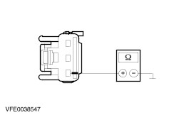
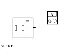
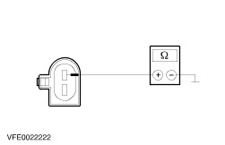
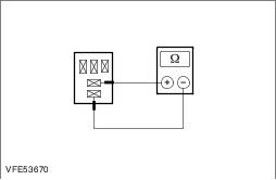
| | | Is the wash/wipe switch OK? Yes CHECK the steering wheel module (SWM) using the diagnostic unit and RENEW if necessary. CHECK operation of system. If the concern persists, CHECK the GEM with the diagnostic unit and RENEW if necessary. CHECK operation of system. No RENEW the wash/wipe switch. CHECK operation of system. | | I6: CHECK THE VOLTAGE AT THE WASHER PUMP (PIN 1) | | | 1 Ignition switch in position II. | | | 2 SWITCH ON the front windshield washer and keep the wash/wipe system switch pressed during the measurement. | | | 3 Measure the voltage between the washer pump, connector C1RW14-B, pin 1, circuit CRW24A (GY), wiring harness side and ground. | | | Does the meter display battery voltage? Yes No | | I7: CHECK CIRCUIT BETWEEN GENERIC ELECTRONIC MODULE (GEM) AND WASHER PUMP FOR OPEN CIRCUIT | | | 1 Ignition switch in position 0. | | | 2 Disconnect Connector C1BP02-A from the GEM. | | | 3 Measure the resistance between the GEM, connector C1BP02-A, pin 71, circuit CRW24A (GY), wiring harness side and the washer pump, connector C1RW14-B, pin 1, circuit CRW24A (GY), wiring harness side. | | | Is a resistance of less than 2 ohms registered? Yes TEST the GEM and RENEW as necessary. CHECK operation of system. No LOCATE and RECTIFY the break in circuit CRW24A (GY) between the GEM and the washer pump with the aid of the Wiring Diagrams. CHECK operation of system. | | I8: CHECK CIRCUIT BETWEEN THE GENERIC ELECTRONIC MODULE (GEM) AND THE WASHER PUMP, PIN 2, FOR OPEN CIRCUIT | | | 1 Ignition switch in position 0. | | | 2 Disconnect Connector C1BP02-A from the GEM. | | | 3 Measure the resistance between the GEM, connector C1BP02-A, pin 72, circuit CRW23A (VT/GN), wiring harness side and the washer pump, connector C1RW14-B, pin 2, circuit CRW23A (VT/GN), wiring harness side. | | | Is a resistance of less than 2 ohms registered? Yes TEST the GEM and RENEW as necessary. CHECK operation of system. No LOCATE and RECTIFY the break in circuit CRW23A (VT/GN) between the GEM and the washer pump with the aid of the Wiring Diagrams. CHECK operation of system. | | PINPOINT TEST J : THE HEADLAMP WASHER SYSTEM IS INOPERATIVE | | TEST CONDITIONS | DETAILS/RESULTS/ACTIONS | | J1: CHECK FUSE F24. | | | 1 Ignition switch in position 0. | | | 2 CHECK Fuse F24 (BJB). | | | Is fuse OK? Yes No RENEW fuse F24 (30 A) and CHECK the operation of the system. If the fuse blows again, LOCATE and REPAIR the short circuit by using the wiring diagrams. CHECK operation of system. | | J2: CHECK THE VOLTAGE AT FUSE F24 | | | 1 Connect Fuse F24 (BJB). | | | 2 Measure the voltage between fuse F24 (30 A) and ground. | | | Does the meter display battery voltage? Yes No REPAIR the voltage supply to fuse F24 with the aid of the Wiring Diagrams. CHECK operation of system. | | J3: CHECK THE VOLTAGE AT THE HEADLAMP WASHER SYSTEM RELAY | | | 1 Disconnect Headlamp washer system relay from socket R10 (BJB). | | | 2 Measure the voltage between the headlamp washer system relay, socket R10, pin 1, circuit SBB24D (VT/RD), wiring harness side and ground. | | | 3 Measure the voltage between the headlamp washer system relay, socket R10, pin 3, circuit SBB24E (VT/RD), wiring harness side and ground. | | | Is battery voltage measured in both cases? Yes No - No battery voltage measured at pin 1:LOCATE and REPAIR the break in circuit SBB24D (VT/RD) between the headlamp washer system relay and fuse F24 with the aid of the Wiring Diagrams. CHECK operation of system. - No battery voltage measured at pin 3:LOCATE and REPAIR the break in circuit SBB24E (VT/RD) between the headlamp washer system relay pin 1 and pin 3 with the aid of the Wiring Diagrams. CHECK operation of system. | | J4: CHECK THE CIRCUIT OF THE HEADLAMP WASHER SYSTEM PUMP | | | 1 Using a fused test cable (30 A) at the headlamp washer system relay, bridge between socket R10, pin 3, circuit SBB24E (VT/RD) and pin 5, circuit CBB24A (VT/GN), wiring harness side. | | | 2 CHECK the operation of the headlamp washer system. | | | Is the headlamp cleaning system operative? Yes No | | J5: CHECK THE VOLTAGE AT THE HEADLAMP WASHER SYSTEM PUMP | | | 1 Connect Headlamp washer system relay to socket R10. | | | 2 Disconnect Connector C1RW14-A from headlamp washer system pump . | | | 3 Ignition switch in position II. | | | 4 SWITCH ON the low beam. | | | NOTE:For the first 10 minutes after the wash/wipe switch is first activated, the headlamp washer system operates every fourth time the wash/wipe switch is activated. If the wash/wipe switch is activated again after 10 minutes then the headlamp washing system is activated and the timer is restarted. 5 SWITCH ON the front windshield washer and keep the wash/wipe system switch pressed during the measurement. | | | 6 Measure the voltage between the headlamp washer system pump, connector C1RW14-A, pin 1, circuit CBB24A (VT/GN), wiring harness side and ground. | | | Does the meter display battery voltage? Yes No LOCATE and REPAIR the break in circuit CBB24A (VT/GN) between the headlamp washer system relay and the headlamp washer system pump with the aid of the Wiring Diagrams. CHECK operation of system. | | J6: CHECK THE GROUND CONNECTION OF THE HEADLAMP WASHER SYSTEM PUMP | | | 1 SWITCH OFF the dipped beam. | | | 2 Ignition switch in position 0. | | | 3 Measure the resistance between the headlamp washer system pump, connector C1RW14-A, pin 2, circuit GD130AB (BK/YE), wiring harness side and ground. | | | Is a resistance of less than 2 ohms registered? Yes RENEW the headlamp washer pump. CHECK operation of system. No LOCATE and REPAIR the break in the circuit between the headlamp washer system pump and soldered connection SP371 with the aid of the Wiring Diagrams. CHECK operation of system. | | J7: CHECK CIRCUIT BETWEEN GENERIC ELECTRONIC MODULE (GEM) AND HEADLAMP WASHER SYSTEM RELAY FOR OPEN CIRCUIT | | | 1 Disconnect GEM from connector C1BP02-A. | | | 2 Measure the resistance between the headlamp washer system relay, socket R10, pin 2, circuit CRW04A (YE/GN), wiring harness side and the GEM, connector C1BP02-A, pin 47, circuit CRW04A (YE/GN), wiring harness side. | | | Is a resistance of less than 2 ohms registered? Yes No LOCATE and REPAIR the break in circuit CRW04A (YE/GN) between the headlamp washer system relay and the GEM with the aid of the Wiring Diagrams. CHECK operation of system. | | J8: CHECK CIRCUIT BETWEEN GENERIC ELECTRONIC MODULE (GEM) AND HEADLAMP WASHER SYSTEM RELAY FOR SHORT TO VOLTAGE | | | 1 Ignition switch in position II. | | | 2 Measure the voltage between the headlamp washer system relay, socket R10, pin 2, circuit CRW04A (YE/GN), wiring harness side and ground. | | | Is a voltage measured? Yes LOCATE and RECTIFY the short to voltage in circuit CRW04A (YE/GN) between the CJB and the headlamp washer system relay using the Wiring Diagrams. CHECK operation of system. No | | J9: CHECK THE HEADLAMP WASHER SYSTEM RELAY | | | 1 Ignition switch in position 0. | | | 2 Connect Headlamp washer system relay to socket R10. | | | 3 Use a fused test cable (1 A) to bridge between the CJB, connector C1BP02-A, pin 47, circuit CRW04A (YE/GN) wiring harness side and ground. | | | Is the headlamp cleaning system operative? Yes CHECK the GEM using the diagnostic unit and RENEW if necessary. CHECK operation of system. No RENEW the headlamp washer system relay. CHECK operation of system. | | PINPOINT TEST K : THE HEADLAMP WASHER SYSTEM IS OPERATING ALL THE TIME | | TEST CONDITIONS | DETAILS/RESULTS/ACTIONS | | K1: CHECK CIRCUIT BETWEEN GENERIC ELECTRONIC MODULE (GEM) AND HEADLAMP WASHER SYSTEM RELAY FOR SHORT TO GROUND | | | 1 Ignition switch in position 0. | | | 2 Disconnect Headlamp washer system relay from socket R10 (BJB). | | | 3 Disconnect Connector C1BP02-A from the GEM. | | | 4 Measure the resistance between the headlamp washer system relay, socket R10, pin 2, circuit CRW04A (YE/GN), wiring harness side and ground. | | | Is a resistance of more than 10,000 ohms measured? Yes No LOCATE and REPAIR the short in circuit CRW04A (YE/GN) between the GEM and the headlamp washer system relay with the aid of the Wiring Diagrams. CHECK operation of system. | | K2: CHECK THE HEADLAMP WASHER SYSTEM RELAY | | | 1 CHECK the headlamp washer system relay according to the component tests at the end of this subsection. | | | Is the headlamp washer system relay OK? Yes CHECK the GEM using the diagnostic unit and RENEW if necessary. CHECK operation of system. No RENEW the headlamp washer system relay. CHECK operation of system. | | PINPOINT TEST L : HEATED NOZZLE(S) INOPERATIVE. | | TEST CONDITIONS | DETAILS/RESULTS/ACTIONS | | L1: CHECK FUSE F37 | | | 1 Ignition switch in position 0. | | | 2 CHECK fuse F37 (BJB). | | | Is fuse OK? Yes No RENEW fuse F37 (10 A) and CHECK the operation of the system. If the fuse blows again, LOCATE and REPAIR the short circuit by using the wiring diagrams. CHECK operation of system. | | L2: CHECK THE VOLTAGE AT FUSE F37 | | | 1 Connect fuse F37 (BJB). | | | 2 Ignition switch in position II. | | | 3 Measure the voltage between fuse F37 (10 A) and ground. | | | Does the meter display battery voltage? Yes No REPAIR the voltage supply to fuse F37 using the Wiring Diagrams. CHECK operation of system. | | L3: CHECK THE VOLTAGE AT THE NOZZLES | | | 1 Ignition switch in position 0. | | | 2 Disconnect Connector C1RD13 from left-hand nozzle. | | | 3 Disconnect Connector C1RD14 from right-hand nozzle. | | | 4 Ignition switch in position II. | | | 5 Measure the voltage between the left-hand nozzle, connector C1RD13, pin 1, circuit CBB37A (WH), wiring harness side and ground. | | | 6 Measure the voltage between the right-hand nozzle, connector C1RD14, pin 1, circuit CBB37D (WH), wiring harness side and ground. | | | Is battery voltage measured in both cases? Yes No - If battery voltage is not measured during one measurement:LOCATE and REPAIR the break in the relevant circuit between soldered connection SP472 and the nozzle using the Wiring Diagrams. CHECK operation of system. LOCATE and REPAIR the break in circuits between fuse F37 and soldered connection SP472 using the Wiring Diagrams. CHECK operation of system. | | L4: CHECK THE GROUND CONNECTION OF THE NOZZLES | | | 1 Ignition switch in position 0. | | | 2 Measure resistance between left-hand nozzle, connector C1RD13, pin 2, circuit GD132A (BK/VT), wiring harness side and ground. | | | 3 Measure resistance between right-hand nozzle, connector C1RD14, pin 2, circuit GD132H (BK/VT), wiring harness side and ground. | | | Is a resistance of less than 2 Ohms measured in both cases? Yes RENEW the relevant nozzle. CHECK operation of system. No - If a resistance of more than 2 Ohms is measured in one of the measurements:LOCATE and REPAIR the break in the relevant circuit between the nozzle and soldered connection SP376 using the Wiring Diagrams. CHECK operation of system. If a resistance of more than 2 Ohms is measured in both of the measurements:LOCATE and RECTIFY the break in the circuit between soldered connection SP376 and soldered connection SP380 with the aid of the Wiring Diagrams. CHECK operation of system. | Component checks Wash/wipe switch NOTE:The value measured in the continuity test of the wash/wipe switch should be less than 50 Ohm. | Circuit to test | Connect the meter to the following terminal pins | Set the switch to the following position | Switch is OK when the following test readings are seen | | Flick wipe, front wiper | 3 and 6 | Flick wipe | Closed circuit | | | | Off | Open circuit | | | | Intermittent | Open circuit | | | | Normal | Open circuit | | | | High | Open circuit | | Intermittent, front wiper | 3 and 7 | Flick wipe | Open circuit | | | | Off | Open circuit | | | | Intermittent | Closed circuit | | | | Normal | Open circuit | | | | High | Open circuit | | Variable delay | 4 and 5 | Intermittent level 1 | Open circuit | | | 4 and 6 | Intermittent level 1 | Open circuit | | | 4 and 7 | Intermittent level 1 | Open circuit | | Variable delay | 4 and 5 | Intermittent level 2 | Closed circuit | | | 4 and 6 | Intermittent level 2 | Open circuit | | | 4 and 7 | Intermittent level 2 | Open circuit | | Variable delay | 4 and 5 | Intermittent level 3 | Closed circuit | | | 4 and 6 | Intermittent level 3 | Closed circuit | | | 4 and 7 | Intermittent level 3 | Open circuit | | Variable delay | 4 and 5 | Intermittent level 4 | Closed circuit | | | 4 and 6 | Intermittent level 4 | Closed circuit | | | 4 and 7 | Intermittent level 4 | Closed circuit | | Variable delay | 4 and 5 | Intermittent level 5 | Open circuit | | | 4 and 6 | Intermittent level 5 | Closed circuit | | | 4 and 7 | Intermittent level 5 | Closed circuit | | Variable delay | 4 and 5 | Intermittent level 6 | Open circuit | | | 4 and 6 | Intermittent level 6 | Open circuit | | | 4 and 7 | Intermittent level 6 | Closed circuit | | Front windshield wiper normal | 3 and 8 | Flick wipe | Open circuit | | | | Off | Open circuit | | | | Intermittent | Open circuit | | | | Normal | Closed circuit | | | | High | Closed circuit | | | 3 and 7 | Flick wipe | Open circuit | | | | Off | Open circuit | | | | Intermittent | Closed circuit | | | | Normal | Open circuit | | | | High | Open circuit | | Front windshield wiper fast | 3 and 8 | Flick wipe | Open circuit | | | | Off | Open circuit | | | | Intermittent | Open circuit | | | | Normal | Closed circuit | | | | High | Closed circuit | | Front washer system on | 3 and 5 | Off | Open circuit | | | | Front washers on | Closed circuit | | Rear washer system on | 2 and 6 | Off | Open circuit | | | | Rear wipers on | Closed circuit | | | | Rear washers on | Closed circuit | | | 2 and 5 | Off | Open circuit | | | | Rear wipers on | Open circuit | | | | Rear washers on | Closed circuit | | Rear wipers on | 2 and 6 | Off | Open circuit | | | | Rear wipers on | Closed circuit | | | | Rear washers on | Closed circuit | Front windshield wiper relay (on/off), front windshield wiper relay (fast/slow), rear window wiper relay - CHECK the normally open contact in the unswitched state.
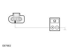
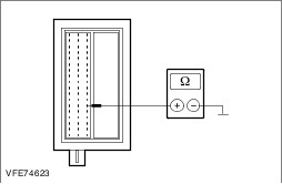
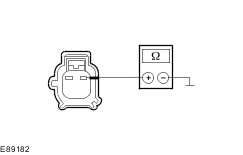
- Measure the resistance at the relay between pin 3, component side, and pin 5, component side.
- Is a resistance of more than 10,000 ohms measured?
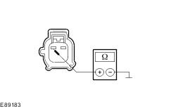
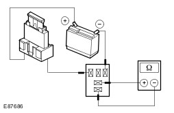
2. If no, INSTALL a new relay. - CHECK the normally open contact in the switched state.
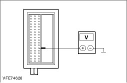
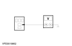
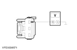
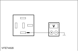
- Using a fused test cable (3 A), connect pin 1 of the relay, component side, with the battery positive terminal.
- Use a test cable to connect pin 2 of the relay, component side, to the battery negative terminal.
- Measure the resistance at the relay between pin 3, component side, and pin 5, component side.
- Is a resistance of less than 2 ohms registered?
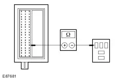
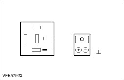
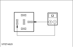
1. If yes, the relay is OK. 2. If no, INSTALL a new relay. Headlamp washer system relay - CHECK the normally open contact in the unswitched state.
- Measure the resistance at the relay between pin 3, component side, and pin 5, component side.
- Is a resistance of more than 10,000 ohms measured?
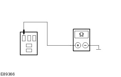
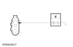
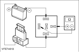
2. If no, INSTALL a new relay. - CHECK the normally open contact in the switched state.
- Using a fused test cable (3 A), connect pin 2 of the relay, component side, with the battery positive terminal.
- Use a test cable to connect pin 1 of the relay, component side, to the battery negative terminal.
- Measure the resistance at the relay between pin 3, component side, and pin 5, component side.
- Is a resistance of less than 2 ohms registered?
1. If yes, the relay is OK. 2. If no, INSTALL a new relay. |