| PINPOINT TEST A : THE ROOF OPENING PANEL DOES NOT OPEN OR CLOSE |
NOTE:Use a digital multimeter for all electrical measurements. |
| TEST CONDITIONS | DETAILS/RESULTS/ACTIONS |
| A1: CHECK FOR VOLTAGE TO THE ROOF OPENING PANEL CONTROL SWITCH |
| | 1 Ignition switch in position II. |
| | 2 CHECK the operation of the roof opening panel control switch lamp. |
| | Does the roof opening panel control switch lamp illuminate? Yes No |
| A2: CHECK THE SUPPLY VOLTAGE TO THE ROOF OPENING PANEL MODULE, CIRCUIT SBP10BA (YE/RD) |
| | 1 Ignition switch in position 0. |
| | 2 Disconnect Fuse 10. |
| | 3 Disconnect Roof Opening Panel Module C9PR32. |
| | 4 Connect Fuse 10. |
| | 5 Measure the voltage between the roof opening panel module C9PR32 pin 1, circuit SBP10BA (YE/RD), harness side and ground. |
| | Is the voltage greater than 10 volts? Yes No |
| A3: CHECK THE SUPPLY VOLTAGE TO THE ROOF OPENING PANEL MODULE, CIRCUIT SBP10A (YE/RD) |
| | 1 Disconnect Fuse F10. |
| | 2 Disconnect Central Junction Box C1BP02-C. |
| | 3 Connect Fuse F10. |
| | 4 Measure the voltage between the central junction box C1BP02-C pin 75, circuit SBP10BA (YE/RD), component side and ground. |
| | Is the voltage greater than 10 volts? Yes Repair circuit SBP10A (YE-RD) or SBP10B (YE-RD). TEST the system for normal operation. No CARRY OUT the central junction box self-test. REFER to diagnostc tool. |
| A4: CHECK THE ROOF OPENING PANEL CONTROL SWITCH DOWN/OPEN GROUND CIRCUIT |
| | 1 Operate the roof opening panel control switch to the DOWN/OPEN position and keep it pressed. |
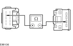
| | 2 Measure the resistance between the roof opening panel module C9PR32 pin 9, circuit CPR40B (YE/OG), harness side and roof opening panel module C9PR32 pin 10, circuit GD138ZA (BK/WH), harness side. |
| | Is the resistance less than 5 ohms? Yes No |
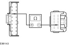
| A5: CHECK FOR CONTINUITY BETWEEN THE ROOF OPENING PANEL MODULE AND THE ROOF OPENING PANEL CONTROL SWITCH |
| | 1 Disconnect roof opening panel control switch C9PR40. |
| | 2 Measure the resistance between the roof opening panel module C9PR32 pin 9, circuit CPR40B (YE/OG), harness side and roof opening panel control switch C9PR40 pin 3 (YE/OG), harness side. |
| | Is the resistance less than 5 ohms? Yes No Repair circuit CPR40A (YE/OG). TEST the system for normal operation. |
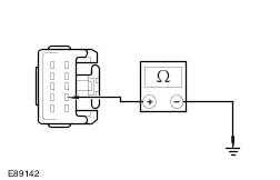
| A6: CHECK THE ROOF OPENING PANEL MODULE GROUND CIRCUIT GD138ZA (BK/WH) |
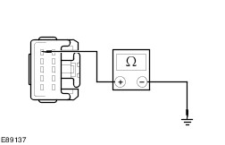
| | 1 Measure the resistance between the roof opening panel module C9PR32 pin 10, circuit GD138ZA (BK/WH), harness side and ground. |
| | Is the resistance less than 5 ohms? Yes Renew the roof opening panel control switch. TEST the system for normal operation. No Repair circuit GD138ZA (BK/WH). TEST the system for normal operation. |
| A7: CHECK THE ROOF OPENING PANEL CONTROL SWITCH UP/CLOSE GROUND CIRCUIT |
| | 1 Connect Roof Opening Panel Control Switch C9PR40. |
| | 2 Operate the roof opening panel control switch to the UP/CLOSE position and keep it pressed. |
| | 3 Measure the resistance between the roof opening panel module C9PR32 pin 8, circuit CPR31B (VT/BN), harness side and roof opening panel module C9PR32 pin 10, circuit GD138ZA (BK/WH), harness side. |
| | Is the resistance less than 5 ohms? Yes Renew the roof opening panel motor.
REFER to: Roof Opening Panel Motor (501-17 Roof Opening Panel, Removal and Installation).
No |
| A8: CHECK FOR CONTINUITY BETWEEN THE ROOF OPENING PANEL MODULE AND THE ROOF OPENING PANEL CONTROL SWITCH |
| | 1 Disconnect Roof Opening Panel Control Switch C9PR40. |
| | 2 Measure the resistance between the roof opening panel module C9PR32 pin 8, circuit CPR31B (VT/BN), harness side and roof opening panel control switch C9PR40 pin 2 (VT/BN), harness side. |
| | Is the resistance less than 5 ohms? Yes Renew the roof opening panel control switch. TEST the system for normal operation. No Repair circuit CPR31B (VT/BN). TEST the system for normal operation. |
| A9: CHECK THE VOLTAGE TO THE ROOF OPENING PANEL CONTROL SWITCH LAMP, CIRCUIT CLN17D (BN) |
| | 1 Ignition switch in position 0. |
| | 2 Disconnect Roof Opening Panel Control Switch C9PR40. |
| | 3 Ignition switch in position II. |
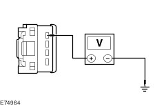
| | 4 Measure the voltage between the roof opening panel control switch C9PR40 pin 1, circuit CLN17B (BN), harness side and ground. |
| | Is the voltage greater than 10 volts? Yes No Repair circuit CLN17B (BN). TEST the system for normal operation. |
| A10: CHECK THE ROOF OPENING PANEL CONTROL SWITCH GROUND CIRCUIT |
| | 1 Ignition switch in position 0. |
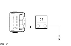
| | 2 Measure the resistance between the roof opening panel control switch C9PR40 pin 4, circuit GD138AB (BK/WH), harness side and ground. |
| | Is the resistance less than 5 ohms? Yes Install a new roof opening panel control switch. TEST the system for normal operation. No Repair circuit GD138AB (BK/WH). TEST the system for normal operation. |