
Mustang L4-140 2.3L Turbo VIN W FI (1984)
TAIL LAMP HOUSING.
NOTE:
It is very important that the inertia switch be installed straight-up-and-down with reset lever button on top.
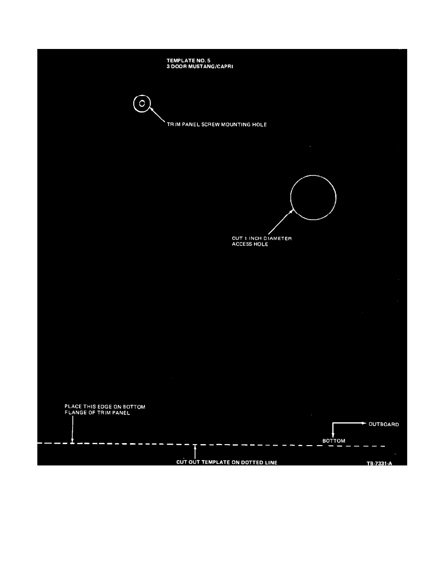
FIGURE 13
4.
Any loose wires that are routed above the inertia switch must be taped up so as not to interfere with the function of the inertia switch reset button.
5.
Using Template No. 5 (Figure 13) cut a one inch diameter access hole in the trim panel for the inertia switch reset button.
NOTE:
The stand off support at the left bottom of trim panel is in line with the new location of the inertia switch; therefore, a portion of the support
may have to be notched for proper installation of trim panel.
6.
After installing the trim panel make sure the reset button can be reached thru the access hole. Install plug button (Part No. 386868-S) in access
hole.
7.
Seal holes in wheel well with silicone sealer.