
Mustang V6-232 3.8L VIN 3 TBI (1984)
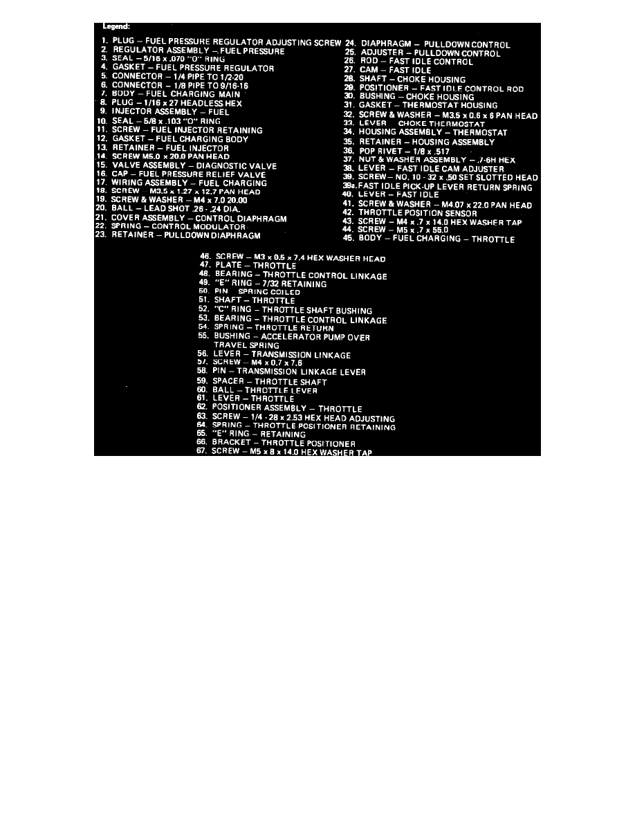
Fig. 15b Fuel charging assembly exploded view. V8 engine units shown, V6 engine units similar
1.
Remove fast idle retaining nut (37), fast idle cam adjuster lever (38) fast idle lever (40) and E-ring (49).
2.
Scribe a mark on potentiometer (42) and throttle body (45) and remove connector bracket retaining screws (43).
3.
Remove potentiometer retaining screws (41) and potentiometer (42).
4.
Position potentiometer on throttle shaft with its scribe mark at 12 o'clock position. Hold potentiometer firmly against throttle body and rotate
potentiometer clockwise until its scribe mark aligns with scribe mark on throttle body, then install retaining screws.
5.
Install E-ring (49), fast idle lever (40), fast idle return spring (39a), if equipped, fast idle adjustment lever (38) and fast idle retaining nut (37).
Torque nut to 16-20 inch lbs.