
Mustang V6-232 3.8L VIN 3 TBI (1984)
diameter holes in the left hand inner rear rail extension.
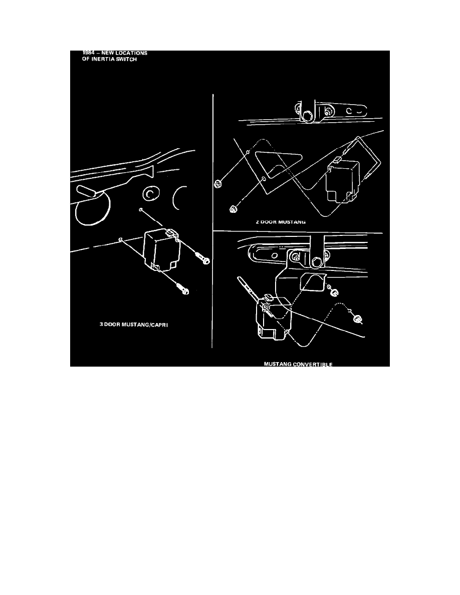
NOTE:
It is very important that the switch be installed straight-up-and-down with rest lever button on top.
FIGURE 8
3.
Install the inertia switch on the outer side of the rail extension using a U-bolt (Part No. E4VE-11N523- AA) and (2) Nut & Washer Assy. (Part No.
N621900-S36) (Figure 8).