
Mustang V6-232 3.8L VIN 3 TBI (1984)
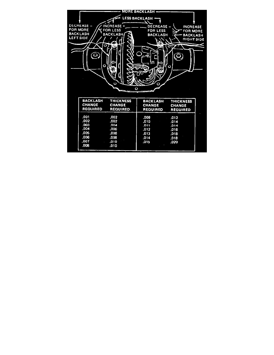
Fig. 11 Rear axle backlash adjustment
6.
On 1982---87 axles, proceed as follows:
a. Mount suitable dial indicator on axle housing cover flange, then measure ring gear backlash. If backlash is within specifications, proceed to
step f. If backlash is not within specifications, proceed to step c. If backlash is zero, proceed to next step.
b. If backlash measured above is zero, add .020 inch (.5 mm) to right side of case and subtract .020 inch (.5 mm) from left side of case, then
recheck backlash. If backlash is now within specifications, proceed to step d.
c. If backlash is not within specifications, correct backlash by increasing thickness of one shim and decreasing thickness on the other shim by
the same amount. Refer to Fig. 11, for approximate shim change.
d. Install shims and bearing caps. Torque bearing cap bolts to 70---85 ft. lbs., then rotate differential case assembly several turns in both
directions.
e. Check backlash. If backlash is within specifications, proceed to step f. If not within specifications, repeat step c.
f.
Increase both left and right side shims by .006 inch to provide proper differential bearing preload. Ensure shims are fully seated and the case
assembly turns freely.
g. Using suitable white marking compound applied to ring gear, check tooth mesh contacting pattern. Tooth mesh contacting pattern can be
improved by installing the propeller shaft and axle assemblies and rotating both tires in the drive and coast direction.
h. Contacting pattern should be within the primary area of the ring gear tooth surface avoiding narrow contact with the outer perimeter of tooth.
Inspect pattern on the drive (pull) side of the ring gear. If serious error is determined, recheck pinion shim selection.
7.
Install axle housing cover, driveshaft and axle assemblies. Refer to ``Rear Axles, Propeller Shaft & Brakes'' section for procedures.
8.
Fill rear axle assembly with suitable axle lubricant. On models equipped with 7.5 and 8.5 inch Traction-Lok differentials, subtract 4 ounces of
axle lubricant and replace with 4 ounces of Friction Modifier C8AZ-19546-A or equivalent.
Drive Pinion Installation
1.
Lubricate pinion bearings with suitable axle lubricant, then install pinion shaft and rear bearing, collapsible spacer and front bearing.
2.
Install slinger (if equipped) and pinion oil seal, then insert pinion flange in seal and hold firmly in place against front bearing. From rear of
housing, insert pinion shaft into flange.
3.
Install pinion nut. While holding pinion flange, tighten nut only enough to remove bearing endplay. When an increase in pinion nut turning effort
is noted, stop tightening pinion nut. Rotate pinion several times in both directions to seat bearings.
4.
Continue to tighten pinion nut in very small increments, then, every so often, using suitable inch lbs. torque wrench, measure pinion rotational
torque. The rotating torque must not exceeds specifications. Do not exceed specified preload torque. Do not loosen pinion nut if preload
torque is exceeded. If preload torque is exceeded, remove pinion nut, yoke, oil seal, slinger (if equipped) and collapsible spacer. Replace
collapsible spacer and oil seal with new ones and repeat procedure.