
Mustang V8-302 5.0L CFI HO (1985)
Lifter / Lash Adjuster: Service and Repair
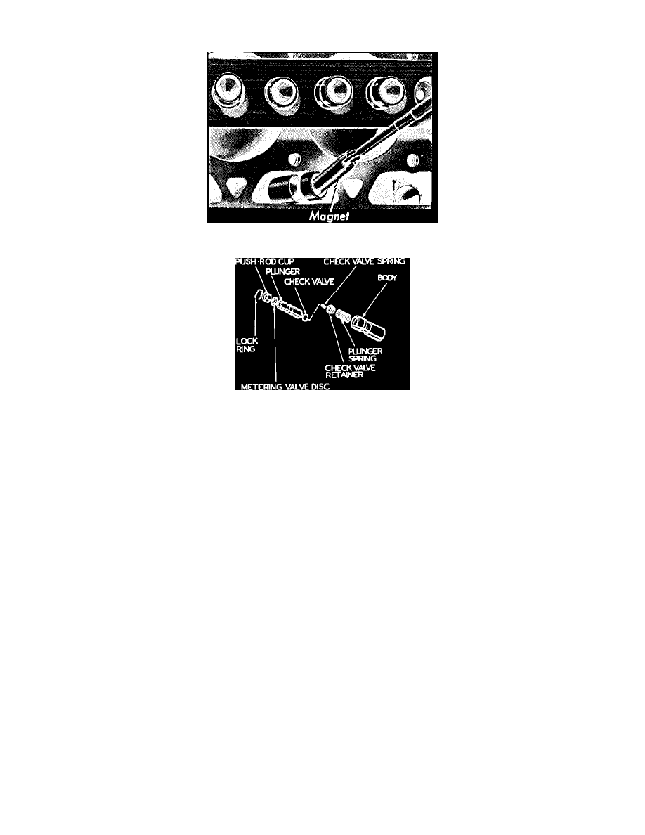
Fig. 21 Removing valve lifter with magnetic rod
Fig. 7 Hydraulic Valve Lifter Disassembled
V6-232, V8-255, 302
1.
On V6-232 engine, disconnect secondary ignition wires from spark plugs using wire remover T74P-6666-A or equivalent. Remove ignition wire
routing clips from rocker arm cover attaching bolt studs and position wires aside.
2.
On all models, remove intake manifold.
3.
Remove rocker arm covers. On engines with stud mounted rocker arms, loosen stud nuts and rotate rocker arms to one side. On other engines,
remove fulcrum bolt, fulcrum, rocker arm and fulcrum guide (if used).
4.
Remove pushrods in sequence so they can be installed in their original bores. On 1985-88 V8 engines equipped with roller lifters, the pushrods
have a collar at the upper end and can only be installed one way. When installing lifters, ensure that lifter is correctly oriented so that
roller rotates in same direction.
5.
Remove lifter guide retainer bolts, retainer and guide plate, if equipped.
6.
Using a magnet rod, Fig. 21, remove the lifters and place them in a numbered rack so they can be installed in their original bores. If the lifters are
stuck in their bores by excessive varnish, etc., it may be necessary to use a plier-type tool to remove them. Rotate the lifter back and forth to loosen
it from the gum or varnish.
7.
The internal parts of each lifter are matched sets. Do not intermix parts. Keep the assemblies intact until they are to be cleaned, Fig. 22.