
Mustang V8-302 5.0L CFI HO (1985)
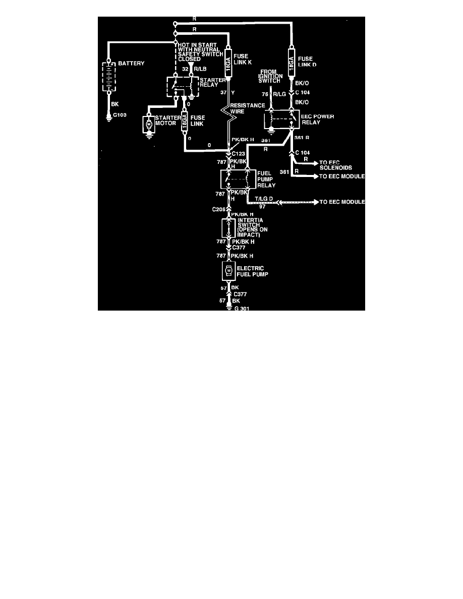
Fig. 5 High pressure fuel pump wiring circuit (Typical)
The throttle body consists of six separate components which perform the fuel and air metering to the engine. The throttle body is mounted on the
intake manifold and provides a housing for the 1) Air Control Butterfly Valves, 2) Injector Nozzles, 3) Fuel Pressure Regulator, 4) Cold Engine Speed
Control), 5) Throttle Position Sensor and 6) Fuel Pressure Diagnostic Valve.
The air flow is controlled by two butterfly valves which are mounted on the throttle body and are similar in design and operation to those of a
carburetor.
The fuel injector nozzles are mounted vertically above the throttle plates. They are electro-mechanical units that meter and atomize the fuel delivered
to the engine, Figs. 1, 2 and 5. The injector consists of a solenoid actuated pintle and needle valve assembly. An electrical control signal from the EEC
electronic processor actuates the solenoid causing the pintle to move off its seat allowing fuel flow. The injector flow orifice is fixed and the fuel supply
pressure is constant, therefore fuel flow to the engine is determined by the amount of time the solenoid is energized.
The pressure regulator, Figs. 1 and 2, is mounted on the fuel charging main body near the rear of the air horn. The regulator is located so as to offset
the affects of pressure fluctuations in the fuel system. It is designed so that it is not affected by back pressure in the fuel return line.
The pressure regulator maintains a working pressure of 30-45 psi and also maintains a fuel supply pressure after engine and fuel pump turn off, by
acting as a check valve between itself and the fuel pump. This maintenance of pressure helps to prevent fuel line vapor lock and permits rapid restarts
and stable engine idling immediately thereafter.
The diagnostic pressure valve located at the top of the fuel metering body provides a convenient point to monitor fuel pump pressure and allows for
bleeding down of the system pressure and bleeding air during service. Do not apply compressed air to the fuel system through the diagnostic valve.