
Mustang V8-302 5.0L COBRA (1995)
Anti-Lock Brake Control Module: Diagrams
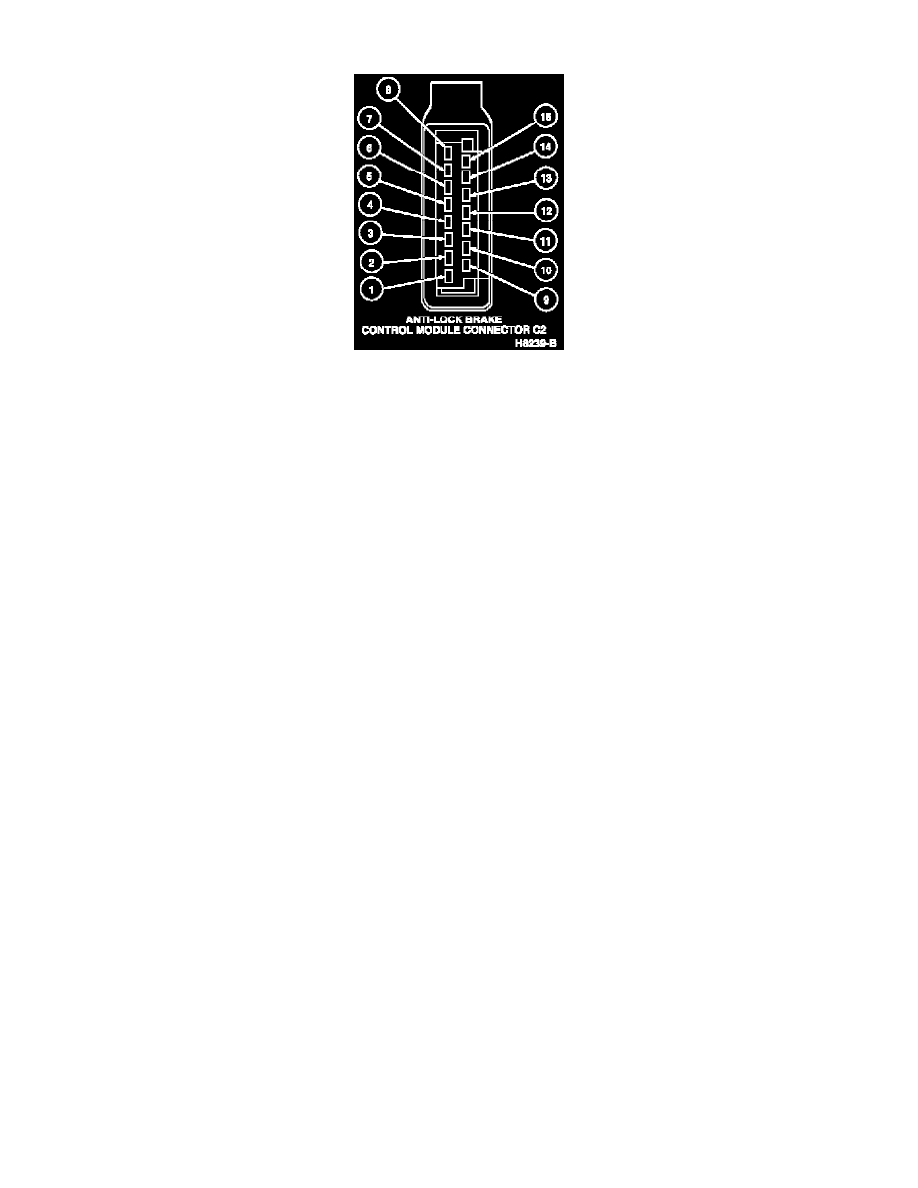
Connector
Pin
Circuit
Circuit Function
1
603 (DG)
Anti-Lock Indicator Output
2
836 (O/W)
ABS Data Link Connector
3
Not Used
4
521 (T/O)
Left Front Brake Sensor
5
496 (O)
Left Rear Brake Sensor Ground
6
494 (T/LG)
Right Rear Brake Sensor Ground
7
492 (BR)
Right Rear Brake Sensor
8
514 (Y/R)
Right Front Brake Sensor
9
511 (LG)
Brake On/Off (BOO) Switch Input
10
Not Used
11
Not Used
12
522 (T/LB)
Left Front Brake Sensor Ground
13
499 (GN/LB)
Left Rear Brake Sensor
14
516 (Y/BK)
Right Front Brake Sensor Ground
15
Not Used
NOTE: On early production vehicles, Circuit 601 may change color from LB/PK to R through the harness connector. Circuit 603 may change color
from DG to Y as it passes through the harness connector.