
Mustang V8-4.6L (2009)
-
Is the resistance less than 5 ohms?
Yes
GO to H13.
No
REPAIR the circuit in question. CLEAR the DTCs. REPEAT the self-test.
-------------------------------------------------
H13 CHECK FOR CORRECT SJB OPERATION
-
Disconnect all the SJB connectors.
-
Check for:
-
corrosion
-
damaged pins
-
pushed-out pins
-
Connect all the SJB connectors and make sure they seat correctly.
-
Operate the system and verify the concern is still present.
-
Is the concern still present?
Yes
INSTALL a new SJB. TEST the system for normal operation.
No
The system is operating correctly at this time. The concern may have been caused by a loose or corroded connector. CLEAR the DTCs. REPEAT the
self-test.
-------------------------------------------------
Pinpoint Test I: The Stoplamps Are On Continuously
Stoplamps
Pinpoint Tests
Pinpoint Test I: The Stoplamps Are On Continuously
Refer to Wiring Diagram Set 90, Turn Signal/Stop/Hazard Lamps for schematic and connector information. See: Diagrams/Electrical
Diagrams/Diagrams By Number
Normal Operation
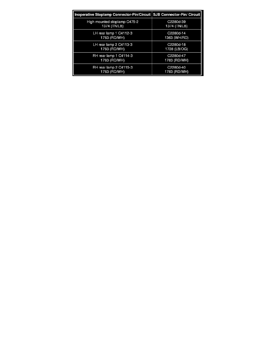
When the brake pedal is applied, the stoplamp switch routes voltage to the Smart Junction Box (SJB) through circuit 511 (LG). Voltage is also routed to
the PCM through circuit 599 (PK/LG). The SJB then provides voltage to the stoplamps through circuits 1783 (RD/WH), 1374 (TN/LB), 1728 (LB/OG),
and 1363 (WH/RD). Ground for the stoplamps is provided through circuit 1205 (BK).