
Mustang V8-4.6L (2009)
PINPOINT TEST C: THE IC DOES NOT RESPOND TO THE SCAN TOOL
NOTICE: Use the correct probe adapter(s) when making measurements. Failure to use the correct probe adapter(s) may damage the
connector.
NOTE: Failure to disconnect the battery when instructed will result in false resistance readings. Refer to Battery.
-------------------------------------------------
C1 CHECK THE HS-CAN TERMINATION RESISTANCE
-
Ignition OFF.
-
Disconnect: Negative Battery Cable.
-
Disconnect the scan tool cable from the Data Link Connector (DLC).
-
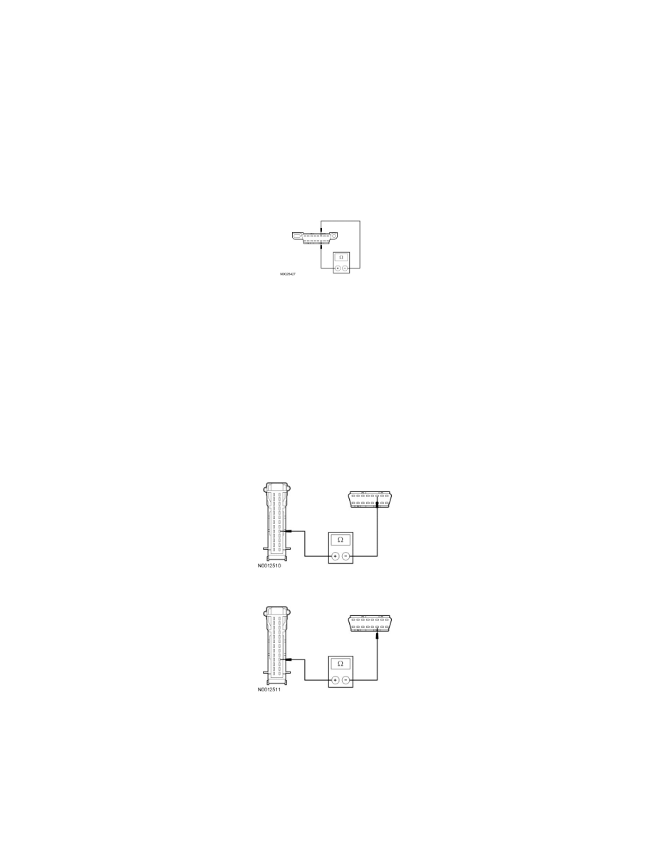
Measure the resistance between the DLC C251-6, circuit 1827 (WH/LG), harness side and the DLC C251-14, circuit 1828 (PK/LG), harness side.
-
Is the resistance between 54 and 66 ohms?
Yes
GO to C3.
No
GO to C2.
-------------------------------------------------
C2 CHECK THE HS-CAN CIRCUITS BETWEEN IC AND THE DLC FOR AN OPEN
-
Measure the resistance between the IC C220-18, circuit 1827 (WH/LG), harness side and the Data Link Connector (DLC) C251-6, circuit 1827
(WH/LG), harness side.
-
Measure the resistance between the IC C220-17, circuit 1828 (PK/LG), harness side and the DLC C251-14, circuit 1828 (PK/LG), harness side.
-
Are the resistances less than 5 ohms?
Yes
CONNECT the negative battery cable. GO to C7.
No
REPAIR the circuit in question. CLEAR the DTCs. REPEAT the network test with the scan tool.