
Mustang V8-4.6L (2009)
-------------------------------------------------
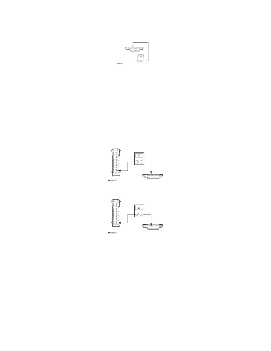
C3 CHECK THE MS-CAN TERMINATION RESISTANCE
-
Measure the resistance between the DLC C251-3, circuit 1847 (WH/OG), harness side and the DLC C251-11, circuit 1848 (PK/OG), harness side.
-
Is the resistance between 54 and 66 ohms?
Yes
GO to C5.
No
GO to C4.
-------------------------------------------------
C4 CHECK THE MS-CAN CIRCUITS BETWEEN THE IC AND THE DLC FOR AN OPEN
-
Measure the resistance between the IC C220-15, circuit 1847 (WH/OG), harness side and the DLC C251-3, circuit 1847 (WH/OG), harness side.
-
Measure the resistance between the IC C220-14, circuit 1848 (PK/OG), harness side and the DLC C251-11, circuit 1848 (PK/OG), harness side.
-
Are the resistances less than 5 ohms?
Yes
CONNECT the negative battery cable. GO to C7.
No
REPAIR the circuit in question. CONNECT the negative battery cable. CLEAR the DTCs. REPEAT the network test with the scan tool.
-------------------------------------------------
C5 CHECK THE IC GROUND CIRCUIT FOR AN OPEN
-
Measure the resistance between the IC C220-2, circuit 1205 (BK) harness side and ground.