
Mustang V8-4.6L (2009)
Power Distribution Module: Service and Repair
Smart Junction Box (SJB)
Removal
NOTICE: Electronic modules are sensitive to static electrical charges. If exposed to these charges, damage may result.
NOTE: Prior to the removal of the module, it is necessary to upload the module configuration information to a scan tool. This information must be
downloaded into the new Smart Junction Box (SJB) after installation.
NOTE: The Tire Pressure Monitoring System (TPMS) functionality is integral to the SJB.
NOTE: A new SJB is delivered in a manufacturing mode with 6 pre-set DTCs. These DTCs require that successful configuration of the SJB occurs, then
successful TPMS sensor training occurs, then a successful self-test occurs, including clearing of DTCs. These steps are required in order to clear the 6
pre-set manufacturing mode DTCs. The 6 pre-set manufacturing mode DTCs are as follows:
-
B2477 (Module Configuration Failure)
-
B2868 (Left Front Tire Pressure Sensor Fault)
-
B2869 (Right Front Tire Pressure Sensor Fault)
-
B2870 (Right Rear Tire Pressure Sensor Fault)
-
B2871 (Left Rear Tire Pressure Sensor Fault)
-
C2780 (ECU in Manufacturer Sub-State)
1. NOTE: If the SJB is being replaced, follow this step. If the SJB is not being replaced, go to Step 2.
Upload the module configuration information from the SJB into the scan tool.
2. Remove the RH A-pillar lower trim panel.
3. NOTE: The SJB electrical connector levers must click into a fully released position before they can be removed.
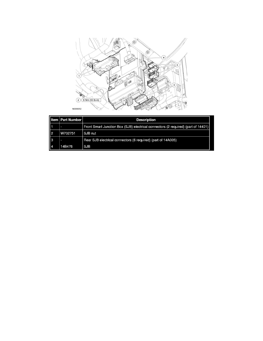
Disconnect the 2 front SJB electrical connectors.
4. Remove the SJB nut.
5. Slide the SJB downward and position the SJB forward to access the rear electrical connectors.
6. NOTE: The SJB electrical connector levers must click into a fully released position before they can be removed.