
Mustang V8-4.6L DOHC VIN R (2003)
Variable Valve Timing Actuator: Description and Operation
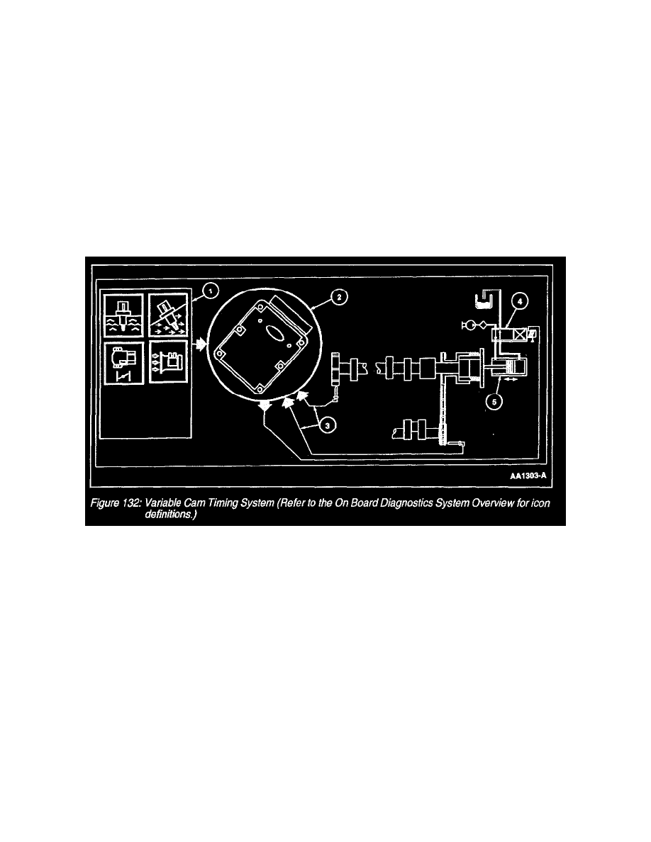
Variable Cam Timing System
Overview
There are four possible types of Variable Cam Timing (VCT) Systems. The 2003 Escort/Tracer are Exhaust Phase Shifting system (EPS). The
exhaust cam is the active cam and is being retarded. The 2003 Lincoln LS, T-Bird and Focus SVT vehicles have Intake Phase Shifting system (IPS).
A intake phase shifting system will move the intake cam in the advance direction. The other two possible systems are Dual Equal (DEPS) both intake
and exhaust cams are phase shifted equally as well as Dual Independent Phase Shifting (DIPS) where the cams are shifted independently. The systems
have three operational modes; idle, part throttle, wide open throttle and a default mode. At idle and (low engine speeds with closed throttle) the phase
angle is controlled by air flow and Engine Coolant Temperature (ECT). At part and wide open throttle the Powertrain Control Module (PCM)
controls cam timing based on engine RPM, load, and Throttle Position (TP). VCT systems provide reduced emissions and enhance engine power, fuel
economy and idle quality. IPS systems have the added benefit of improve torque. In addition a VCT system will eliminate the need for an external
Exhaust Gas Recirculation (EGR) system. The elimination of EGR system is accomplished by controlling the overlap in valve opening between the
intake valve opening and exhaust valve closing. Increased vehicle reliability is achieved with the elimination of the EGR system.
Variable Cam Timing
Variable Cam Timing System
The VCT (variable cam timing) system consists of an electric hydraulic positioning control solenoid, a CMP (Camshaft Position Sensor) and trigger
wheel. The CMP trigger wheel has a number of equally spaced teeth equal to the number (n) of cylinders on a bank plus one extra tooth (n+1). Four
cylinder and V8 engines use a CMP 4+1 tooth trigger wheel. V6 engines use a CMP 3+1 tooth trigger wheel. The extra tooth placed between the
equally spaced teeth represents the CMP signal for that bank. A CKP (Crankshaft Position Sensor) provides the PCM (powertrain control module)
with crankshaft positioning information in 10 degree increments (Figure 130).
1. The PCM receives input signals from the Intake Air Temperature (IAT), ECT (engine coolant temperature), CMP, TP (throttle position), MAF
(Mass Air Flow) and CKP to determine the operating conditions of the engine. At idle (low engine speeds and closed throttle) the PCM
controls camshaft position based on air and coolant temperatures. During part and wide open throttle, camshaft position is determined by
engine RPM, load and throttle position. The VCT system will not operate until the engine is at normal operating temperature.
2. The VCT system is enabled by the PCM when the proper conditions are met.
3. The CKP signal is used as a reference for CMP positioning.
4. The PCM calculates and determines the desired camshaft position. It will continually update the VCT solenoid duty cycle until desired
positioning is achieved. A difference between the desired and actual camshaft position represents a position error in the PCM's VCT control
loop. The PCM will disable the VCT and place the camshaft in a default position if a fault is detected.
5. Oil flows to either side of the piston chamber in the VCT assembly, which changes the linear piston motion to a rotational motion that
advances or retards the camshaft.
Hardware
Variable Cam Timing (VCT) Solenoid Valve