
Mustang V8-4.6L DOHC VIN R (2003)
Position the pinion flange.
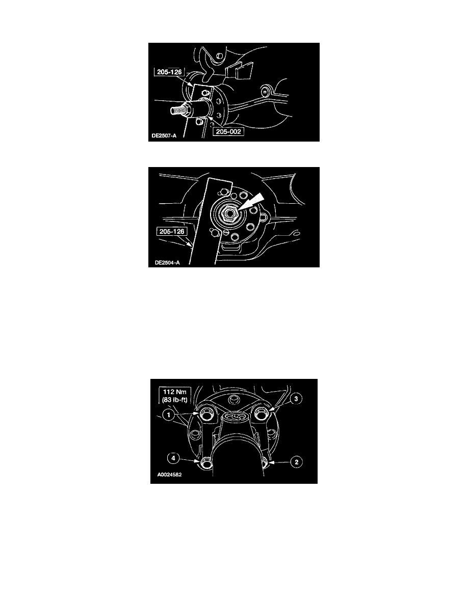
4. Using the special tools, install the pinion flange.
5. CAUTION: Do not under any circumstance loosen the nut to reduce preload. If it is necessary to reduce preload, install a new collapsible spacer
and nut.
CAUTION: Remove the special tool while taking preload readings with the Nm (inch/pound) torque wrench.
Tighten the nut to set the preload.
^
Rotate the drive pinion occasionally to make sure the differential pinion bearings seat correctly. Take frequent differential pinion bearing
torque preload readings by rotating the drive pinion with a Nm (inch/pound) torque wrench.
^
If the preload recorded prior to disassembly is lower than the specification for used bearings, then tighten the nut to specification. If the
preload recorded prior to disassembly is higher than the specification for used bearings, then tighten the nut to the original reading as recorded.
^
Refer to the torque specification for used differential pinion bearings.
6. CAUTION: Align the index marks.
CAUTION: Install the driveshaft with new bolts. If new bolts are not available, apply Threadlock and Sealer EOAZ-19554-AA or equivalent
meeting Ford specification WSK-M2G351-A5 to the threads of the original bolts.
CAUTION: The driveshaft centering socket yoke fits tightly on the pinion flange pilot. To make sure that the yoke seats squarely on the flange,
tighten the bolts evenly in a cross pattern as shown.
Connect the driveshaft.
7. Install the rear brake calipers.