Mustang V8-5.4L SC (2008)

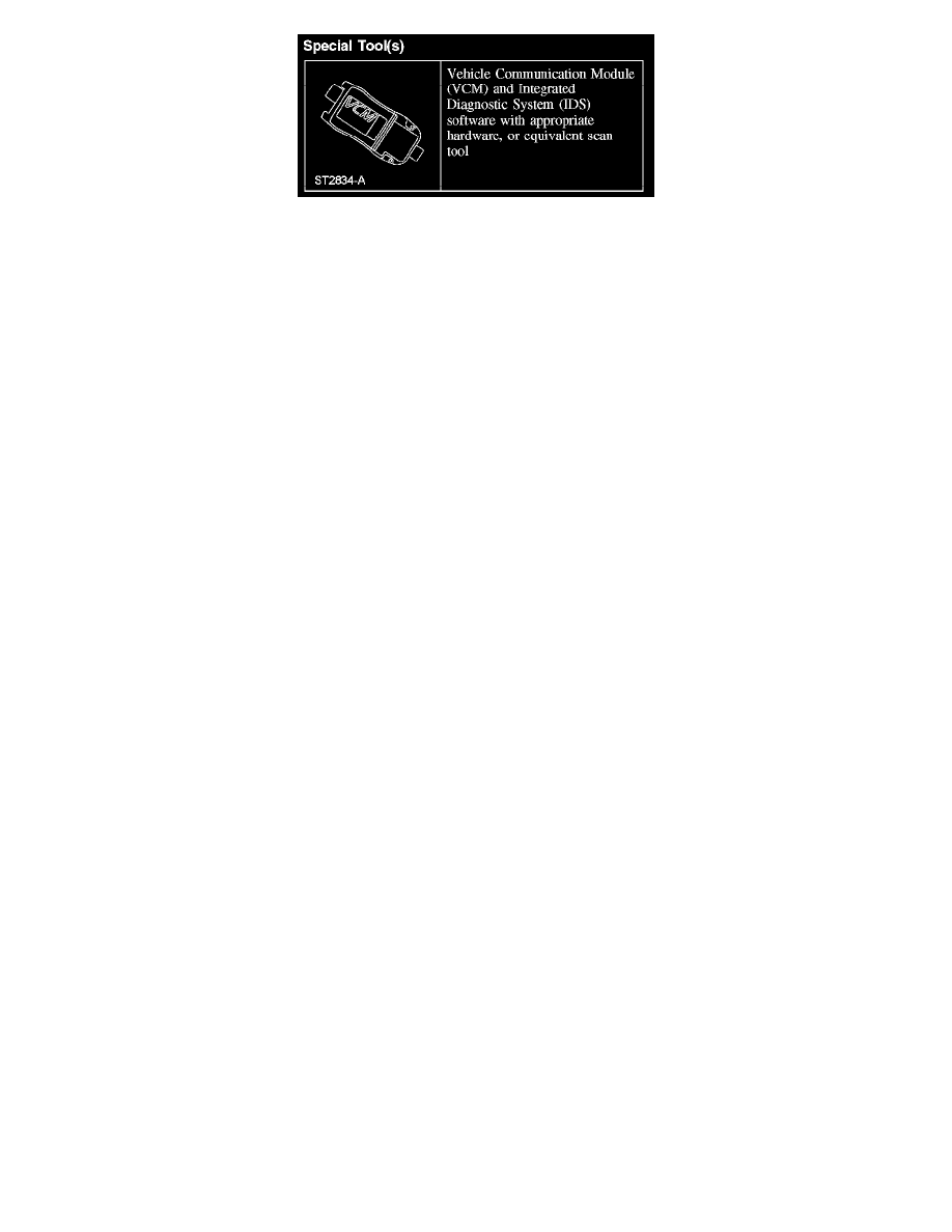
Special Tool(s)
Removal and Installation
WARNING:
-
Always wear eye protection when servicing a vehicle. Failure to follow this instruction may result in serious personal injury.
-
Never probe the electrical connectors on air bag, safety canopy or side air curtain modules. Failure to follow this instruction may result in
the accidental deployment of these modules, which increases the risk of serious personal injury or death.
CAUTION: To prevent system failure, it is necessary to carry out the occupant classification sensor (OCS) system reset when a front passenger
seat cushion is disassembled, a new trim cover installed or an OCS system service kit is installed. A scan tool is used to carry out the OCS
system reset command.
NOTE:
-
The air bag warning indicator illuminates when the restraints control module (RCM) fuse is removed and the ignition switch is ON. This is normal
operation and does not indicate a supplemental restraint system (SRS) fault.
-
The SRS must be fully operational and free of faults before releasing the vehicle to the customer.
-
If a driver or passenger seat backrest heater mat is faulty, a new seat backrest foam pad must be installed with the heater mat. Do not reuse the
original seat backrest foam pad.
All seats
1. Remove the front seat.
2. Remove the clip and recline handle.
Driver seat with manual height adjust
3. Remove the manual height adjust handle center cover.
4. Remove the 2 screws and manual height adjust handle.
All seats
5. CAUTION: Inspect the cushion side shield retaining clips for damage. Install new retainers if damage is present.
Remove the screw at the rear of the cushion side shield. Release the retaining clips and pin-type retainer and separate the side shield.
-
Vehicles with a manual seat, remove the cushion side shield.
6. Separate the side air bag module electrical connector and the wire harness pin-type retainers from the seat track bracket and cushion frame.
Driver seat with power lumbar and heated seats
7. NOTE: Note the harness routing for installation.
Release the cushion trim cover rear lower J-clip and disconnect the power lumbar and heated seat cushion electrical connector and separate the
connectors from the seat cushion frame.
