
Mustang Cobra V8-281 4.6L DOHC VIN V MFI (1997)
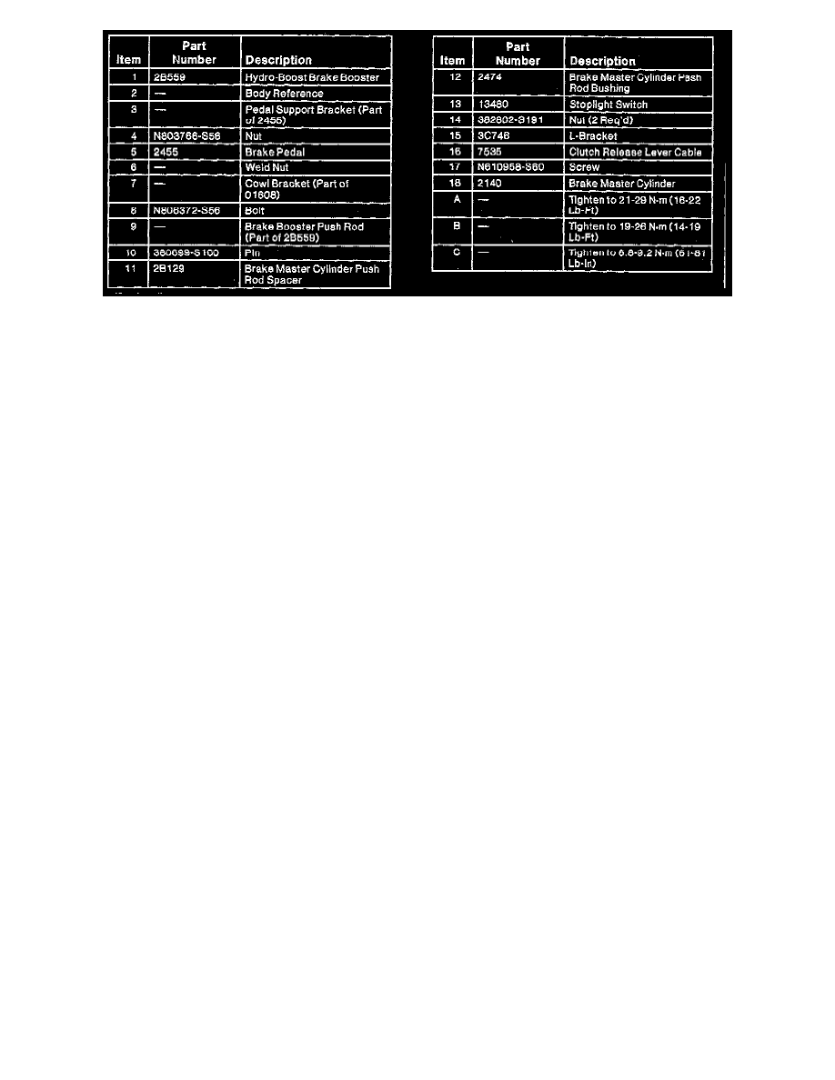
Brake Pedal And Bracket (Part 2 Of 2)
REMOVAL
1. Disconnect battery ground cable.
2. Disconnect the stoplight switch electrical connector from the stoplight switch.
3. Disconnect electrical connectors from speed control deactivate switches at brake and clutch pedal.
4. Remove the clutch cable from the clutch pedal (manual transmission vehicles). Refer to Transmission and Drivetrain.
5. Loosen the four pedal support retaining nuts on the booster studs.
6. Remove retaining screw at brake pedal support bracket to cowl.
7. Remove the push rod retainer and push rod bushing. Slide the stoplight switch inboard along the brake pedal pin just far enough for the outer hole
of the stoplight switch frame to clear the pin. Remove the stoplight switch by sliding it upward. Remove the black stoplight switch brake push rod
spacer from the push rod.
8. Remove four retaining nuts from booster studs. Remove brake pedal and bracket assembly.
INSTALLATION
1. Install brake pedal and bracket on brake booster studs. Install and hand-start two lower retaining nuts.
2. Slide brake booster input rod onto brake pedal pin. Install the black brake push rod bushing on brake pedal pin and position on brake pedal pin.
3. Position stoplight switch so it straddles the push rod and black push rod bushing with the slot toward the pedal blade and the hole just clearing the
pin. Slide the stoplight switch completely onto the pin. Install the white push rod spacer on the pin and install retaining pin securely.
4. Install two retaining nuts on upper booster studs and retaining screw for pedal and bracket to cowl. Tighten four retaining nuts to 21-29 Nm (16-21
ft. lbs.) starting with top right retaining nut and working counterclockwise.
5. Tighten retaining screw to cowl to 19-26 Nm (14-19 1b-ft).
4. Connect electrical connectors to stoplight switch and speed control deactivate switches.
5. Attach the clutch cable to the clutch pedal (manual transmission vehicles).
6. Remove speed control deactivate switch from adapter on brake pedal arm. Push adjustment mechanism toward the switch pivot. Depress brake
pedal and hook the claw over adapter. Pull up on brake pedal to complete adjustment procedure.
7. Connect the battery ground cable.