
Mustang Cobra V8-281 4.6L DOHC VIN V MFI (1997)
NOTE: Due to the use of a cracked connecting rod joint face surface, it is imperative that the connecting rod cap be properly aligned to the
connecting rod. The rod connecting rod bearing tangs should be located on the same side of the connecting rod.
4. Install lower connecting rod bearings into connecting rods. Align retaining tang of connecting rod bearing with notch in connecting rod cap.
5. Alternately tighten new connecting rod bolts in several passes to obtain 25-35 Nm (18-25 ft. lbs.) and rotate connecting rod bolts an additional
85-95°. After installation rotate crankshaft to make sure of smooth operation.
6. Check connecting rod side clearance using Rotunda Dial Indicator with Bracketry TOOL-4201-C or equivalent. Clearance should be 0.15-0.45
mm (0.006-0.0177 inch). If side clearance Is greater than maximum service limit of 0.50 mm (0.020 inch), replace connecting rods and for
crankshaft.
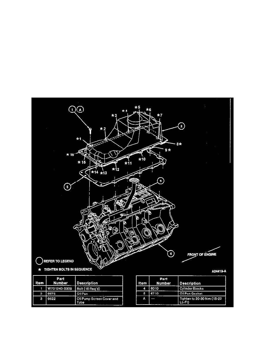
NOTE: Install new oil pump inlet tube gasket on oil pump screen cover and tube. Then start all bolts on oil pump and oil pump screen cover and
tube before tightening.
7. Install oil pump inlet tube gasket and oil pump screen cover and tube. Follow proper procedure.
8. Clean oil filter gasket surface with clean, lint-free cloth. If scraping is required, use a plastic-tipped scraper on the aluminum surface.
9. Install new oil bypass filter.
10. Install new oil pan gasket on oil pan and place on cylinder block (6010). Install oil pan retaining bolts and tighten in sequence as shown to 20-30
Nm (15-22 ft. lbs.).
11. Install engine.