
Mustang Cobra V8-281 4.6L DOHC VIN V MFI (1997)
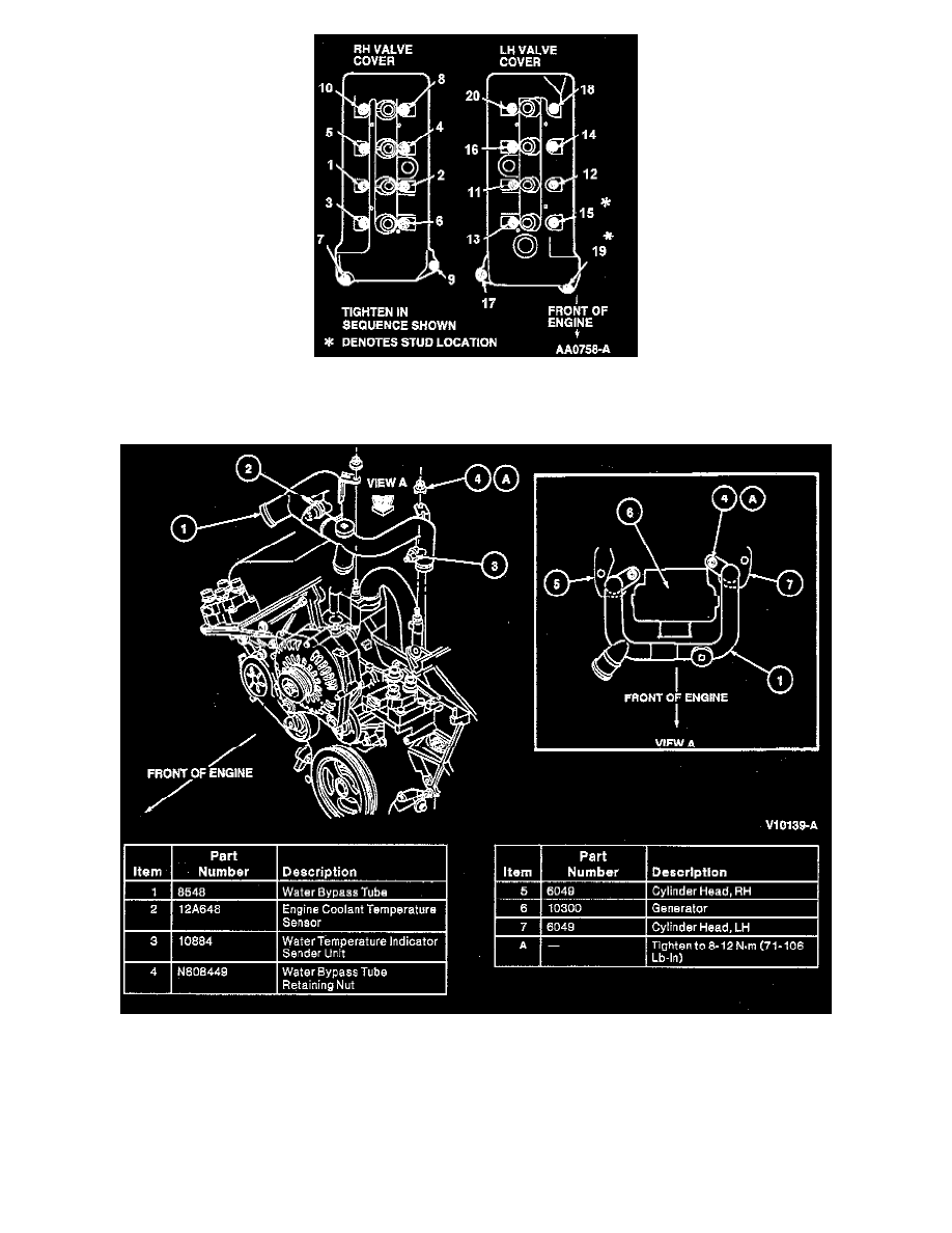
47. On RH valve cover, install bolts into valve cover. Tighten bolts in sequence to 8-12 Nm (71-106 inch lbs.) within four minutes of applying sealer.
48. On LH valve cover, install bolts and stud bolt into valve cover. Tighten bolts and stud bolt in sequence to 8-12 Nm (71-106 inch lbs.) no more
than four minutes after applying sealant.
49. Replace O-ring seals on water bypass tube. Replace center O-ring seal on water bypass tube.
50. Clean O-ring sealing surface on cylinder heads and lubricate water bypass tube sealing O-rings with a rubber lubricant meeting Ford specification
ESE-M99B 176-A. Insert water bypass tube support braces over intake manifold inner studs and press water bypass tube into position.
CAUTION: Do not cut O-ring seal during water bypass tube installation into cylinder heads or possible engine coolant leakage may occur.
51. Install two water bypass tube retaining nuts and tighten to 8-12 Nm (71-106 inch lbs.).
52. Verify conductivity of water temperature indicator sender unit (10884) using Rotunda Digital Volt-Ohmmeter 014-00407 or equivalent. Touch
body of water temperature indicator sender unit with probe and other probe to ground. If more than 1 ohm resistance, remove water bypass tube