
Mustang Cobra V8-281 4.6L DOHC VIN V MFI (1997)
1. Set up ring gear to create a pattern as follows:
a. The final pinion position will be verified by using the gear contact pattern method described as follows:
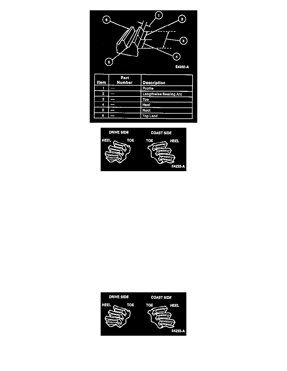
b. The toe of the gear tooth is the portion of the tooth surface at the end toward the center. The heel of the gear tooth is the portion of the tooth
surface at the outer end. The top land of a gear tooth is the surface of the top of the tooth. Every gear has a characteristic pattern. The
illustrations show typical patterns only and explains how patterns shift as gear location is changed. When making pinion position changes,
shims should be changed in the range of 0.05 mm (0.002 inch) to 0.10 mm (0.004 inch) until correct pattern has been obtained.
NOTE: When making changes, note that two variables are involved. For example, if you have the backlash set correctly to specifications and
you change the pinion position shim, you may have to readjust the backlash to the correct specification before checking the pattern. Refer to
illustrations following Step 3.
^
When a change in backlash is required backlash shims should be changed in the range of 1-1/2 times the amount of backlash required to
bring the gears into specification. For example, if the backlash needs to be changed by 0.10 mm (0.004 inch), the shim pack should be
changed by 0.15 mm (0.006 inch) as a starting point. The actual amount of backlash change obtained will vary depending upon the ratio
and gear size.
^
High backlash is corrected by moving the ring gear closer to the pinion. Low backlash is corrected by moving the ring gear away from the
pinion. These corrections are made by adding and subtracting shim thickness from one side of the differential case to the other.
c. Paint ring gear teeth with a marking compound to both the drive and coast side.
2. While turning pinion gear, rotate ring gear one complete revolution in both directions. Apply load with a large screwdriver or similar tool between
the carrier casting and differential case flange.
3. Interpret the pattern left on ring gear as shown in the following illustrations:
^
Normal or desirable pattern. The drive pattern should be centered on the tooth. The coast pattern should be centered on the tooth, but may
be slightly toward the toe. There should be some clearance between the pattern and the top of the tooth.