
Mustang GT V8-4.6L SOHC VIN X (1998)
Brake Pad: Service and Repair
Front
REMOVAL
1. Remove master cylinder cap and check fluid level in reservoir. Remove brake fluid until brake master cylinder reservoir is half full. Discard
removed fluid.
2. Raise vehicle on hoist.
3. Remove wheel and tire assembly from rotor mounting face. Use care to avoid damage or interference with front disc brake rotor shield or wheel
cylinder bleeder screw
4. Remove anchor plate mounting bolts.
NOTE: It is not necessary to disconnect hydraulic connections.
5. Lift front disc brake caliper/front disc brake caliper anchor plate away from front disc brake rotor using rotating motion.
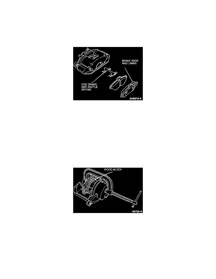
6. Remove outer brake lining assembly from front disc brake caliper assembly by sliding brake lining in anchor away from outer leg to disengage
from front disc brake caliper anchor plate. Remove outer brake lining.
7. Remove inner brake lining assembly by sliding lining in anchor away from caliper piston disengaging it from the front disc brake caliper anchor
plate. Remove inner lining and anti-rattle clip.
8. Inspect both rotor braking surfaces. Minor scoring or buildup of lining material does not require machining or replacement of front disc brake
rotor.
9. Inspect piston boot and caliper pin boots for damage and replace as necessary.
10. Support the front disc brake caliper assembly in a manner that will not stretch or damage the front brake hose.
INSTALLATION
Retracting Caliper
1. Use a 10 cm (4 inches) C-clamp and wood block 70 mm x 25 mm (2-3/4 inch x 1 inch) and approximately 19 mm (3/4 inch) thick to seat caliper
piston in its bore. This must be done to provide clearance for front disc brake caliper assembly to fit over front disc brake rotor during installation.
2. Thoroughly clean any residue from insulator from front disc brake caliper and brake lining abutments as necessary. Make certain disc brake pad
anti-rattle clip is seated in brake lining inspection opening. Hold-down springs must be installed from lining side.
NOTE: Front disc brake rotor casting allows disc brake pad anti-rattle clip to be installed one way only. RH and LH hold-down springs are
identical but installed in opposite directions.
3. Peel protective paper from insulator on the brake lining. The insulator will be black after the paper has been removed. This pressure-sensitive
adhesive insulator functions to reduce noise and care should be exercised to avoid contamination on the adhesive surface prior to installing the
brake lining in the front disc brake caliper assembly.