
Mustang GT V8-4.6L SOHC VIN X (1998)
Brake Rotor/Disc: Service and Repair
Brake Rotor/Disc
Refinishing
All rotor refinishing must adhere to the rule that equal amounts of rotor stock are removed from each braking surface each time a disc brake rotor is
refinished.
The minimum allowable overall rotor thickness continues to be stamped on the disc brake rotor and must not be exceeded.
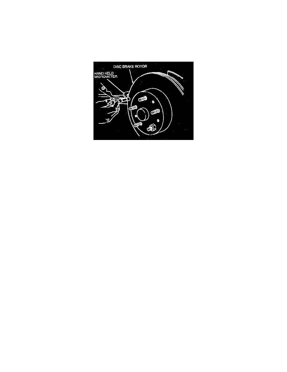
Measuring Thickness Of Disc Brake Rotor Braking Surface
1. With a suitable micrometer, measure the overall thickness of the rotor braking surface at four equally spaced points around the disc brake rotor.
2. Using the lowest reading from Step 1, subtract the minimum allowable thickness stamped into the rotor. The difference, if any, represents the total
amount of material available for machining. A thickness reading less than the minimum rotor thickness requires disc brake rotor replacement.
3. After measuring the disc brake rotor, the rotor should be installed in the lathe arbor using the special adapter that is required for proper rotor
alignment. Never use a lathe that cuts only one face of the disc brake rotor at a time. It must be a simultaneous straddle cut.
Install a dial indicator to read rotor lateral runout near the center of the disc brake rotor braking face.
-
If runout is 0.050 mm (0.002 inch) or below, proceed to machine rotor.
-
If runout is over 0.050 mm (0.002 inch), loosen the rotor on the arbor and rotate 90 degrees.
Reread the runout and if it is below 0.050 mm (0.002 inch), proceed to machine the rotor.
-
If runout is still over 0.050 mm (0.002 inch), again loosen the rotor and rotate it an additional 90 degrees. Recheck the runout.
-
If runout is 0.050 mm (0.002 inch) or less, proceed to machine the rotor. If the runout still exceeds 0.050 mm (0.002 inch), return the rotor to
the best runout position obtained.
-
If the disc brake rotor runout can be brought below 0.05 mm (0.002 inch), proceed to machine the disc brake rotor.
-
If the rotor cannot be brought below 0.05 mm (0.002 inch) runout, it must be replaced.
4. Set the cutting tool to just contact the high spots on the disc brake rotor, then adjust the cutting tool to the minimum depth required to clean up the
rotor face. Equal material must be removed from each side. Do not exceed the allowable stock removal. Clean all cuttings and chips from the disc
brake rotor before installing.
Front
REMOVAL
1. Raise vehicle on hoist.
2. Remove the wheel and tire from the wheel hub. Be careful to avoid damage to or interference with the wheel cylinder bleeder screw and caliper
front disc brake rotor shield.
3. Remove caliper anchor plate bolts.
CAUTION: Handle the front disc brake rotor and front disc brake caliper assemblies in such a way as to avoid damage to the front disc brake
rotor and nicking, scratching, or contamination of the lining.
4. Remove the front disc brake caliper/front disc brake caliper anchor plate from the front wheel spindle and the front disc brake rotor. If the front
disc brake caliper does not require servicing, it is not necessary to disconnect the front brake hose.
5. Position the front disc brake caliper out of the way.
NOTE: To prevent damage, do not allow front disc brake caliper to hang by the front brake hose.
6. Remove front disc brake rotor assembly from wheel hub. If both front disc brake rotors are being serviced, label front disc brake rotor left or right.
NOTE: If excessive force must be used during front disc brake rotor removal, the front disc brake rotor should be checked for lateral runout prior