
Mustang GT V8-4.6L SOHC VIN X (1998)
Brake Rotor/Disc: Component Tests and General Diagnostics
Parallelism
Parallelism is the variations in the thickness of the disc brake rotor. If the two rubbing surfaces of the disc brake rotor are not parallel, the disc brake
rotor may cause excessive brake pedal travel, a pulsating brake pedal or noise.
Two methods can be used to check if the two faces of a disc brake rotor are parallel. A micrometer can be used to measure the disc brake rotor
thickness at 12 points approximately 30 degrees apart and 25.4 mm (1 inch) from the outer edge of the disc brake rotor.
The other method is to measure the disc brake rotor on a precision lathe designed for machining disc brake rotors. Attach two Rotunda Disc Rotor and
Ball Joint Gauges 134-RO199, one on each side of the disc brake rotor, so that the stylus of each gauge contacts the rubbing surface, directly opposite
each other, approximately 25.4 mm (1 inch) from the outer edge of the disc brake rotor.
Zero both gauges and rotate the disc brake rotor while watching both dials. If the total readings of both indicators exceed the specified limit for
parallelism, the disc brake rotor must be refinished or replaced.
Runout
CAUTION: The rotor runout specification must be met to assure proper brake performance without premature vehicle return with shudder or
roughness complaints.
1. Remove caliper and caliper bracket.
2. Mount the rotor with all wheel nuts firmly tightened.
NOTE:
-
The front rotors are match-mounted to the hub. If the color code is still present, mark stud and rotor hole.
-
Make sure all mating surfaces between the hub flange and the rotor are clean and free of rust or contaminants to prevent an erroneous
reading.
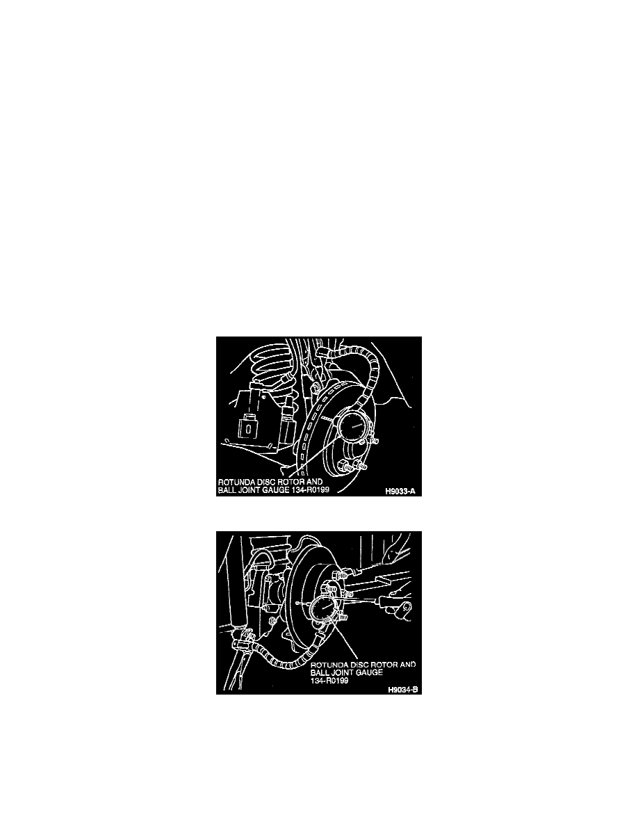
Front Brake Rotor Runout
Rear Brake Rotor Runout
3. Install Rotunda Disc Rotor and Ball Joint Gauge 134-RO199 or equivalent as indicated in the illustrations.
4. Measure runout at approximately 9.5 mm (0.375 inch) inboard from the outer edge of the rotor.
5. If the runout meets specification, reinstall the caliper and caliper bracket.