
Mustang GT V8-4.6L SOHC VIN X (1998)
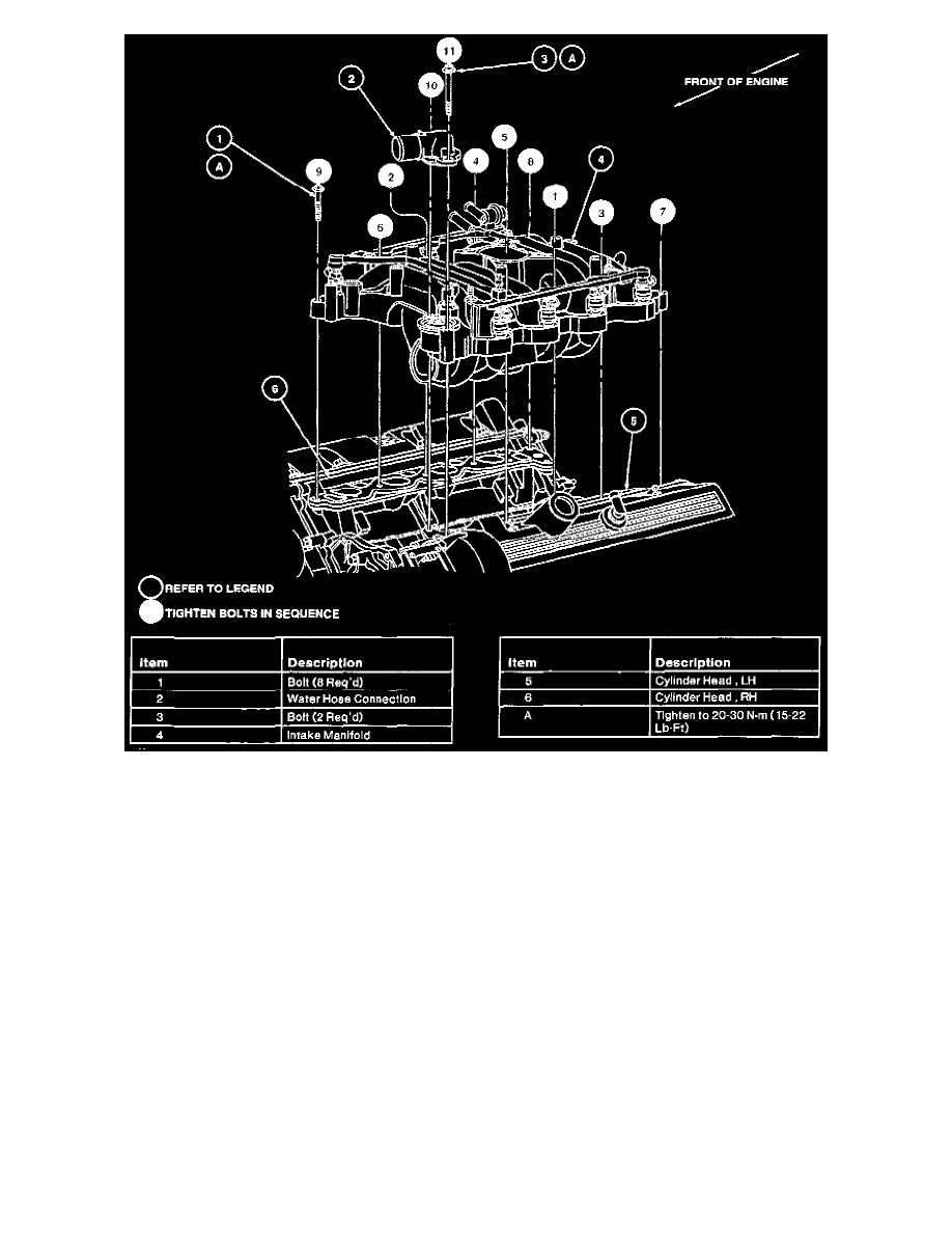
5. Replace O-ring seal on water hose connection. Position water hose connection and upper radiator hose and install two bolts and tighten to 20-30
Nm (15-22 ft. lbs.).
6. Connect heater water hose to heater water tube.
7. Connect vacuum hose to throttle body adapter vacuum port.
8. Install accelerator cable bracket on intake manifold and connect accelerator cable and speed control actuator cables to throttle body.
9. Raise vehicle.
10. Connect EGR valve to exhaust manifold tube to RH exhaust manifold and tighten nut to 35-45 Nm (26-33 ft. lbs.).
11. Connect the engine control sensor extension wire to the electronic variable orifice sensor and oil pressure sensor.
12. Lower vehicle.
13. Position generator and install two retaining bolts. Tighten to 20-30 Nm (15-22 ft. lbs.).
14. Install two bolts retaining generator rear mounting bracket to intake manifold and tighten to 8-12 Nm (71-106 in. lbs.).
15. Connect generator wiring harness to generator, RH front fender apron and junction block.
16. Position ignition wires and ignition wire separators on engine and install bolts retaining ignition coil to ignition coil brackets. Tighten bolts to 8-12
Nm (71-106 in. lbs.).
17. Connect all ignition wires to spark plugs.
18. Connect ignition wire separators on valve cover studs.
19. Connect the engine control sensor extension wire to both ignition coils and camshaft position sensor.
20. Install drive belt.
21. Install air cleaner outlet tube.
22. Connect fuel lines.
23. Connect battery ground cable.
24. Fill and bleed engine cooling system.
25. Check and fill crankcase to specified level with clean engine oil Motorcraft XO-5W30-QSP meeting Ford specification WSS-M2C153-G.
26. Start engine and check for leaks.