
Mustang GT V8-4.6L SOHC VIN X (1998)
Module Identification
Modules included on this SCP communication network include:
Powertrain Control Module (PCM):
^
located in the passenger side of the dash panel.
^
a failure of the communication network to the PCM may result in a no start condition.
^
if communication to the PCM fails during diagnosis, See: Testing and Inspection/Diagnostic Trouble Code Tests and Associated Procedures
Passive Anti-Theft System (PATS) Module:
^
located under the instrument panel to the left of the steering column.
^
works with PCM to enable or disable engine start function.
^
failure of the PATS or communication to the module may result in a no start condition.
^
if communication to the PATS module fails during diagnostics, See: Testing and Inspection/Diagnostic Trouble Code Tests and Associated
Procedures
Diagnostic Communication Network
The international standards organization (ISO) 9141 communication link:
^
consists of a single wire, Circuit 70 (LB/W).
^
provides a common link for communication to an off-board tester through the data link connector (DLC) located under the instrument panel to
the right of the steering column.
^
does not allow module-to-module communications.
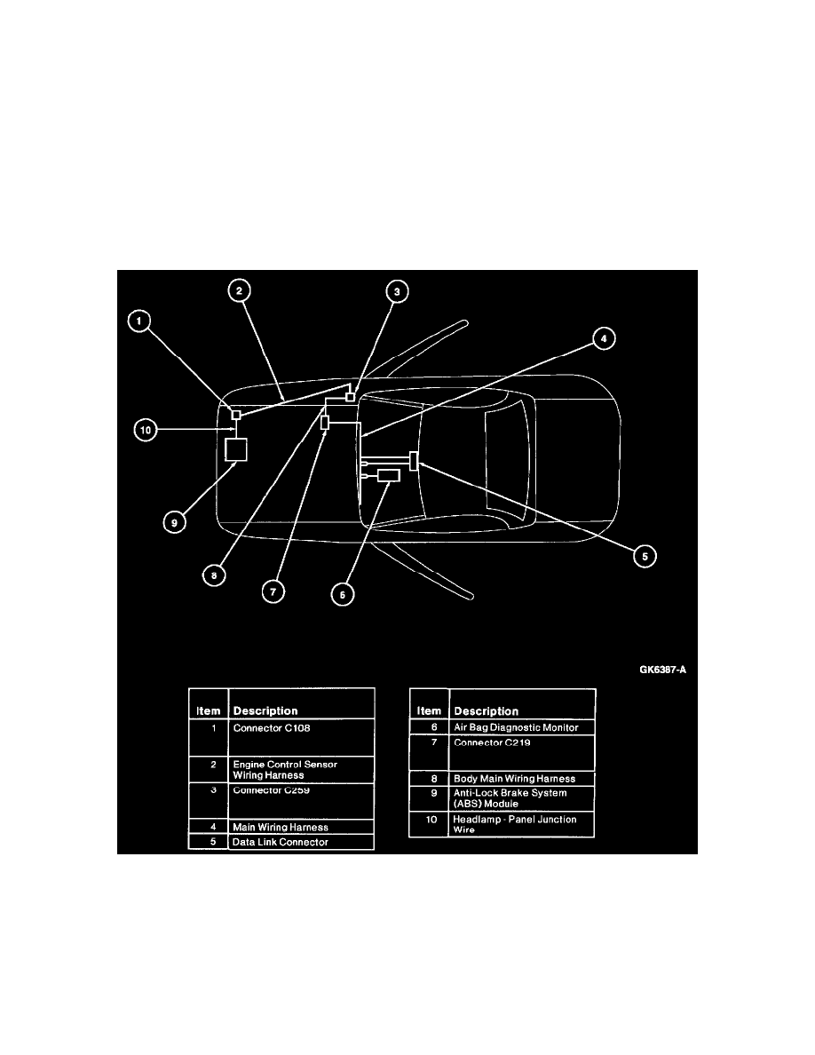
Two micro-processor based subsystems are included on this network:
^
air bag diagnostic monitor system
^
anti-lock brake system