
Mustang GT V8-4.6L SOHC VIN X (1998)
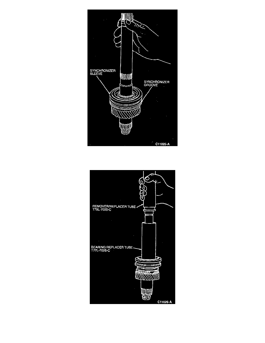
8. NOTE: Groove on synchronizer sleeve must face toward the front of output shaft.
Place first-second synchronizer onto output drive shaft.
9. NOTE: Make sure inserts on synchronizer align with pockets on outer blocker rings.
Using Bearing Replacer Tube 308-067 (M7L-7025-C), Remover/Replacer Tube 308-025 (T75L-7025-C) and Replacer/Adapter 308-239
(T96P-7025-A), press first-second synchronizer onto splines by tightening nut on Replacer/Adapter 308-239 (T96P-7025-A).