
Probe V6-182 3.0L (1990)
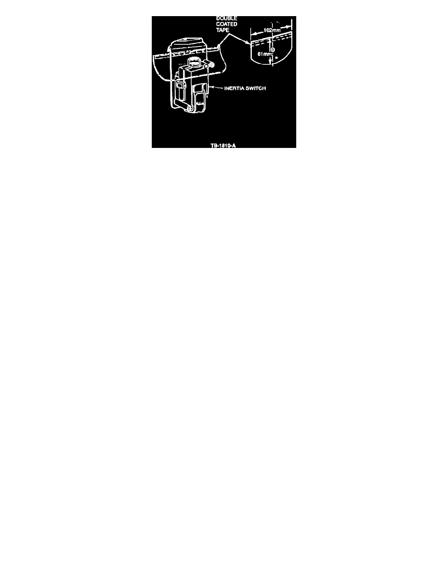
Figure 4
b.
Install the cover on the inertia switch as shown in Figure 4.
NOTE: IF THE CAR ALREADY HAS A PROTECTIVE COVER, INSPECT IT TO BE SURE THAT IT CAN BE SECURELY ATTACHED. IF
THERE IS ANY DOUBT, INSTALL A NEW COVER.
9.
Install the inertia switch and bracket assembly and protective cover in the storage compartment.
NOTE:
WHEN INSTALLING THE INERTIA SWITCH, MAKE SURE THE PROTECTIVE COVER DOES NOT COME OFF.
10.
Connect the negative battery cable.
11.
Make sure the passive restraint system and inertia switch are operating proporly. Refer to the 1990 Probe Shop Manual, Section 41-54, Pinpoint
Tests PR 5 for test procedure.
PART NUMBER
PART NAME
Class
EBAZ-9341-A
Inertia Switch
B
F12Z-9F315-A
Protective Cover
B
OTHER APPLICABLE ARTICLES: None
WARRANTY STATUS:
Eligible Under Basic Warranty Coverage
OPERATION
DESCRIPTION
TIME
902602A
Install Inertia Switch &
1.0 Hr.
Protective Cover
DEALER CODING
BASIC PART NO.
CONDITION CODE
9341
49
OASIS CODES:
603300, 607000. 203000, 104000