
Probe V6-182 3.0L (1990)
7.
Connect the front limit switch electrical connector.
8.
Install the quarter trim panel. Refer to appropriate Service Manual.
9.
Install the A to B trim panel. Refer to the appropriate Service Manual.
10.
Attach the shoulder belt to the buckle carrier.
11.
Connect the battery negative cable, then remove the memory saver.
12.
Check the passive restraint system for proper operation.
Attachment V - Technical Instructions(System Diagnosis)
SUPPLEMENTAL DIAGNOSTIC GUIDE
TABLE OF CONTENTS
^ I.
Symptom Chart------------------------------------
Pg. 1
^ II.
Description And Operation----------------------
Pg. 2-4
^ III.
Electrical Schematic-----------------------------
Pg. 5-7
^ IV.
Passive Restraint Module Pin Out---------------
Pg. 8-9
^ V.
Diagnostic And Testing (PR Tests)-------------
Pg. 10-22
^ VI.
Fuel Pump Inertia Switch Technical------------
Pg. 23-27
Service Bulletin (90-26-02)
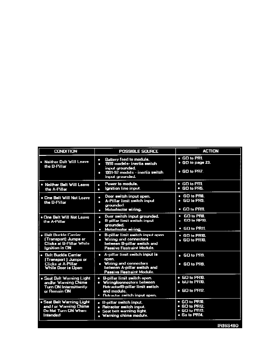
Symptom Chart