
Probe V6-182 3.0L (1990)
NOTE:
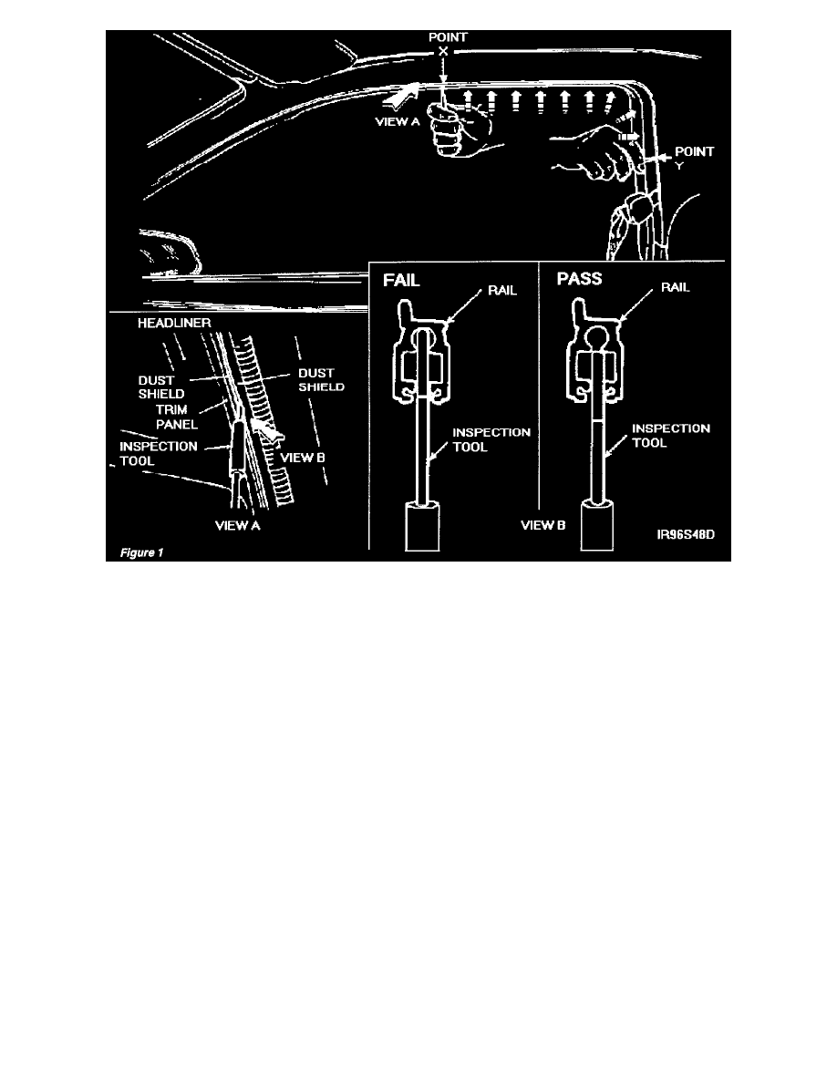
Dust shield wear may cause the position of the scribe line to vary. Insert the inspection tool between dust shields of the rail assembly at point
X. Tool must be installed until it bottoms out in the rail assembly. Note the distance between the dust shields and the scribed line on the tool.
Insert the inspection tool every 1/2" from point X to point Y of the rail assembly. See Figure 1. DO NOT SLIDE THE INSPECTION TOOL
ALONG THE RAIL ASSEMBLY. REMOVE AND REINSERT EVERY 1/2" BETWEEN POINT X AND POINT Y.
3.
a.
If installed inspection tools' depth does not increase (scribe line does not move closer to the dust shield) anywhere between points X and Y,
no service action is required.
b.
If installed inspection tools' depth increases (scribe line moves closer to the dust shield) anywhere between points X and Y, the rail assembly
must be replaced, see Rail Replacement.
Rail Replacement
The following procedure is applicable for either left side (96S48), if necessary, rail replacement.
This illustration shows a cutaway view of the left side rail and motor assembly. Right side rail and motor assembly symmetrically opposite.