
Probe V6-182 3.0L (1990)
6.
Raise and support the rear of the center console high enough to gain access to the white colored sensor caps on the retractor, Figure 1.
Figure 2
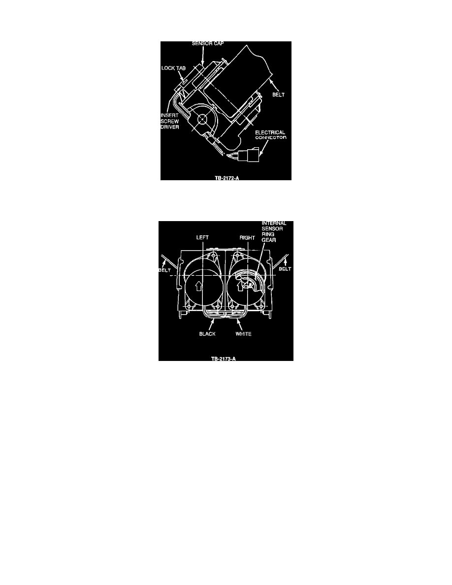
7.
Use a small screwdriver to gently unhook the three (3) lock tabs that secure the sensor caps to the switch housing, Figure 2.
Figure 3
8.
Gently lift each sensor cap upward to disengage it from the main switch housing. Disconnect the wire harness connector.
NOTE:
BE CAREFUL NOT TO MOVE OR DISLOCATE THE INTERNAL SENSOR RING GEAR BECAUSE ITS POSITION DETERMINES
THE TIMING AND ACTIVATION OF THE WARNING LIGHT AND CHIME, FIGURE 3.
9.
Install the new sensor caps.
a.
Gently install the left side cap (black wires) and the right side cap (white wires) onto the retractor switch housing.
b.
Connect the wire harness.
10.
Check the position of the internal sensor ring gear.
NOTE:
IF THE INTERNAL SENSOR RING GEAR MOVES OUT OF POSITION OR IS DISLOCATED, USE THE FOLLOWING PROCEDURE
TO PROPERLY RE-INDEX.
a.
Pull the belt out about 27-1/2" (700 mm).