
Probe V6-182 3.0L (1990)
Hall Effect Sensor: Description and Operation
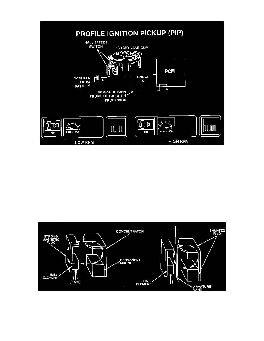
Profile Ignition Pickup
The Profile Ignition Pickup (PIP) signal is created in the Hall Effect and Stator assembly and indicates crankshaft position and engine rpm. The PIP
signal is fed to both the Thick Film Integrated (TFI-IV) module and the Electronic Control Assembly (ECA).
COMPONENTS
The Hall Effect device is made up of a voltage regulator, a Hall voltage generator, Darlington amplifier, Schmitt trigger, and an open collector output
stage integrated in a single monolithic silicon chip. A signal is produced when a ferrous material is passed through the opening and the flux lines
decrease.
The Hall generator (Hall device) sends a sine wave signal to the Darlington amplifier.
The Darlington amplifier inverts the signal. When the signal is low the output is high. When the signal is high the output is low. This output then goes to
the Schmitt trigger.
The Schmitt trigger shapes the signal into a square wave (digital high) signal.
PIP Signal Operation
OPERATION
The output signal to the Darlington amplifier is high when the window (on the armature) allows the magnetic field to reach the Hall device (switch OFF).
When the TAB shunts the magnetic field (closes) away from the Hall device the signal is low to the Darlington amplifier (switch ON).