
Probe V6-182 3.0L (1990)
3. Reverse procedure to assemble. Install stopper plug large end first.
ASSEMBLE
NOTE: Refer to the Exploded Views Of Valve Body images for assembling procedure.
CAUTION: When assembling valve body, do not mix up front and rear gaskets.
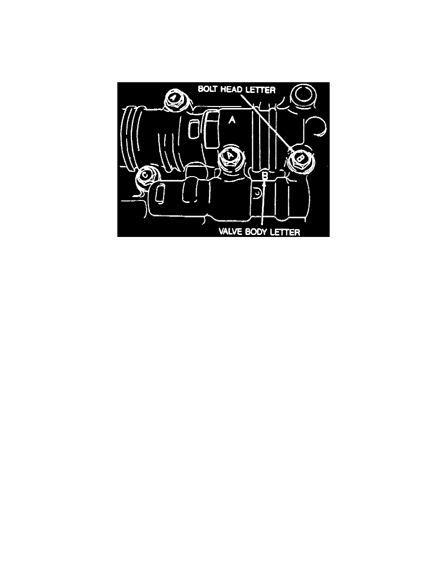
Bolt Head Letter Location
CAUTION: Ensure bolt head letter and control valve body letter match.
1. Install orifice check valves and springs in rear control body, as shown in the Relief Valve And Spring Location From Rear Control Body image.
2. Install gaskets on both sides of rear separator, then install onto rear control body.
CAUTION: The rear gasket and main rear gasket are not interchangeable.
3. Install orifice check valves springs and rubber ball in main control body, as shown in the Relief Valve And Rubber Ball Location From Main
Control Body image.
4. Install rear control body to main control body.
5. Loosely tighten rear control body bolts.
CAUTION: Ensure bolt head letter matches letter on valve body.
6. Turn assembly over, then install orifice check valves springs, converter relief ball, and spring in main control body, as shown in the Relief Valves
And Spring Location From Main Control Body image.
7. Install orifice check valves, springs, throttle relief ball, and spring in premain control body, as shown in the Relief Valve And Check Ball Location
From Premain Control Body.
8. Install gaskets on both sides of main separator, then install onto premain control body.
9. Set premain control body onto main control body.
10. Loosely tighten premain control body bolts.
11. Install orifice check valve and spring in premain control body, as shown in the Relief Valves And Spring Location From Premain Control Body
image.
12. Install gaskets on both sides of premain separator, then install on front control body.
13. Install front control body on premain control body.
14. Loosely tighten bolts and bracket, then match head letter.
15. Install two valve body mounting bolts for alignment.
16. Install front and rear control valve body mounting bolts. Torque bolts to 57-69 in lbs.
17. Install 3-4 solenoid valve and 2-3 solenoid valve with new 0-rings and oil strainer. Torque solenoid valve bolts to 57-69 in lbs.