
Probe V6-182 3.0L (1990)
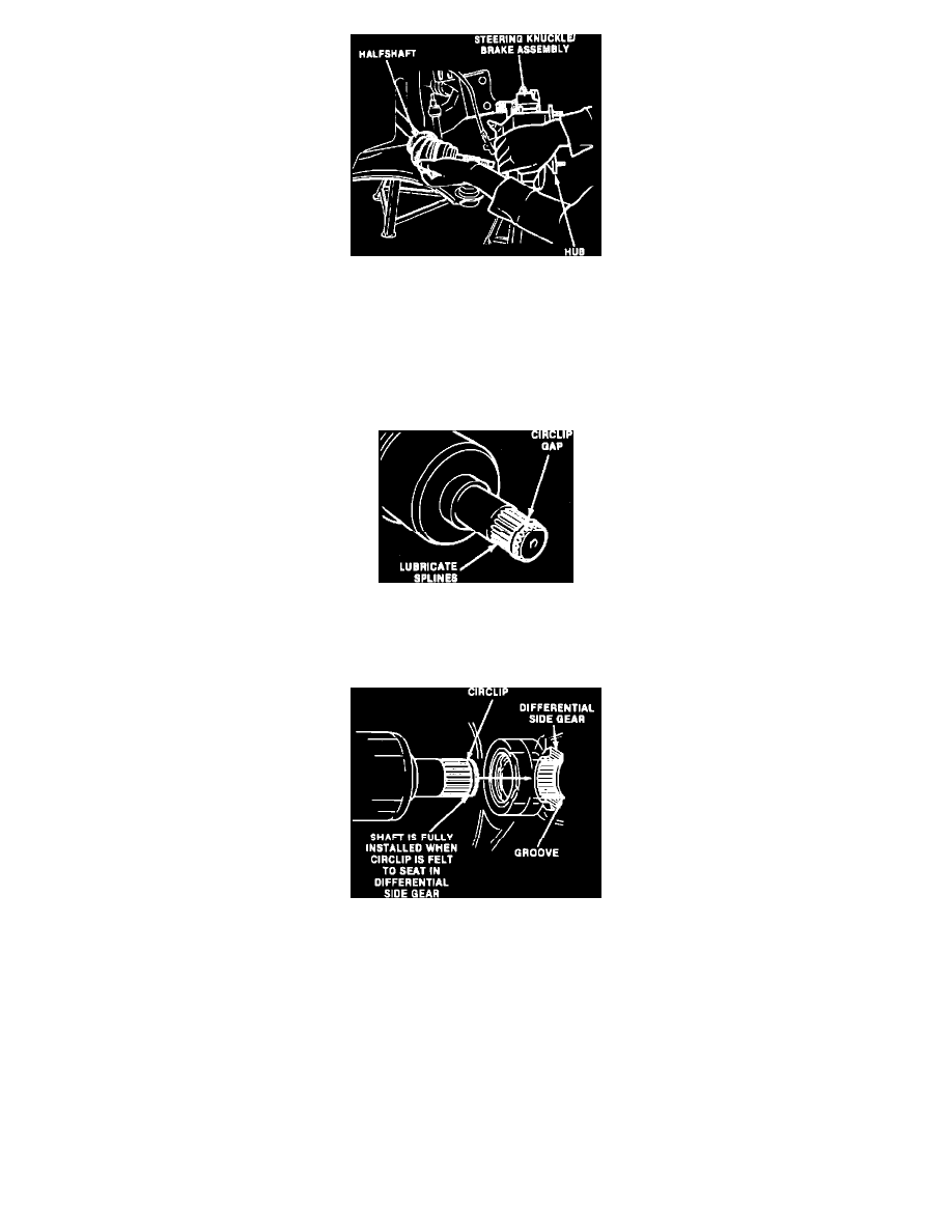
Fig. 4 Separating Halfshaft From Hub & Steering Knuckle
8.
On all models, remove axle nut and washer, then pull halfshaft from hub and steering knuckle assembly, Fig. 4. If binding is encountered, use
puller D80L-1002-L to separate halfshaft from hub and knuckle assembly.
9.
Support halfshaft and carefully slide from transaxle. Use care not to damage transaxle case oil seal when removing halfshaft.
10.
Cap transaxle halfshaft openings.
INSTALLATION
Fig. 5 Position Circlip On Halfshaft Spline
1.
Position replacement circlip halfshaft groove at transaxle end, Fig. 5. To prevent over expanding, position one end of circlip into groove then work
other end over shaft and into groove. When installed, gap in circlip should be at top of halfshaft splines.
Fig. 6 Installing Halfshaft To Differential Side Gear
2.
Lightly lubricate halfshaft splines with lubricant C1AZ-1959D or equivalent on Probe and Tracer models or C1AZ-19590-BA or equivalent on
Capri models, then position halfshaft splines to differential side splines, Fig. 6.
3.
Push halfshaft splines into differential until circlip snaps into differential side gear groove, Fig. 6.
4.
Position halfshaft through hub and steering knuckle and loosely install replacement axle nut and washer, Fig. 4.
5.
On Probe models, install dynamic damper, then torque attaching bolts to 31-46 ft. lbs.
6.
On all models, position lower control arm ball joint to steering knuckle, then install and torque clamp bolt to 32-40 ft. lbs.
7.
Install stabilizer bar link to lower control arm. Tighten nut until .43 inch of bolt thread extends beyond nut on Capri and Tracer models or .79 inch
on Probe models.
8.
Install underbody covers.