| Diagnosis and Testing Refer to Wiring Diagrams Section 501-16, for schematic and connector information. Special Tool(s) | | Terminal probe kit 29-011A | General Equipment Analogue multimeter Digital multimeter Inspection and Verification - Verify the customer concern.
- Visually inspect the following mechanical and electrical causes for the concern.
Visual Inspection Chart | Mechanical | Electrical | - Wiper arm shaft
- Hoses
- Spray nozzles
| - Tailgate contact plate
- Connector(s)
- Switch(es)
| - Repair any faults found during the visual inspection before proceeding to the next steps.
- If the concern is still present after the visual inspection has been carried out, refer to the Symptom Chart and proceed in accordance with the fault symptom.
Symptom Chart | Symptom | Possible Sources | Action | | Windshield wiper motor completely inoperative | * Fuse(s) * Multi-function switch * Windshield wiper motor * Electric circuit(s). | * | | Slow wipe inoperative (fast wipe OK) | * Multi-function switch * Windshield wiper motor * Electric circuit(s). | * | | Fast wipe inoperative (slow wipe OK) | * Multi-function switch * Windshield wiper motor * Electric circuit(s). | * | | Intermittent wipe inoperative (other functions OK) | * Multi-function switch * Electric circuit(s). * Front wiper delay relay * Generic electronics module (GEM) | * | | Wipers not returning to the park position after switching them off (other functions OK) | * Windshield wiper motor * Front wiper delay relay * Generic electronics module (GEM) * Multi-function switch * Electric circuit(s). | * | | Windshield wiper motor inoperative when the windshield wash/wipe system is switched on (wipers off, washer system OK) | * Front wiper delay relay * Generic electronics module (GEM) * Electric circuit(s). | * | | Windshield wiper motor running continuously | * Windshield wiper motor * Front wiper delay relay * Generic electronics module (GEM) * Multi-function switch * Electric circuit(s). | * | | Rear wiper inoperative (windshield wiper motor OK) | * Rear wiper motor * Multi-function switch * Tailgate contact plate * Electric circuit(s). | * | | Rear wiper not returning to the park position after switching it off | * Rear wiper motor * Tailgate contact plate * Electric circuit(s). | * | | Rear wiper continuously on | * Rear wiper motor * Multi-function switch * Electric circuit(s). | * | | Windshield washer inoperative | * Multi-function switch * Electric circuit(s). * Washer pump motor | * | | Washer fluid level warning light inoperative (bulb test OK) | * Washer fluid level switch * Auxiliary warning module * Electric circuit(s). | * | | Washer fluid level warning light continuously lit up | * Washer fluid level switch * Auxiliary warning module * Electric circuit(s). * Instrument cluster | * | Pinpoint Test | PINPOINT TEST A : WINDSHIELD WIPER MOTOR COMPLETELY INOPERATIVE | | TEST CONDITIONS | DETAILS/RESULTS/ACTIONS | | A1: CHECK THE VOLTAGE SUPPLY OF THE MULTI-FUNCTION SWITCH | | | 1 Ignition switch in position II. | | | 2 Switch on the rear wiper. | | | Does the rear wiper work? Yes No | | A2: CHECK FUSE F12 | | | 1 Ignition switch in position 0. | | | 2 CHECK Fuse F12 (CJB). | | | 3 Check fuse F12 (20 A) | | | Is the fuse OK? Yes No RENEW fuse F12 (20 A). Check the operation of the system. If the fuse blows again immediately after installing, LOCATE and RECTIFY short circuit to ground with the aid of the Wiring Diagrams Binder. | | A3: CHECK THE VOLTAGE SUPPLY TO FUSE F12 | | | 1 Connect Fuse F12 (CJB). | | | 2 Ignition switch in position II. | | | 3 Measure the voltage between fuse F12 (20 A) and ground. | | | Is battery voltage displayed? Yes No REPAIR the voltage supply to fuse F12 with the aid of the Wiring Diagrams Binder. CHECK the operation of the system. | | A4: CHECK THE VOLTAGE SUPPLY OF THE MULTI-FUNCTION SWITCH | | | 1 Ignition switch in position 0. | | | 2 Disconnect Multi-function switch C65b. | | | 3 Ignition switch in position II. | | | 4 Measure the voltage between the multi-function switch, connector C65b, pin 10, circuit 14-AK19 (VT/OG), wiring harness side and ground. | | | Does the meter display battery voltage? Yes CHECK and if necessary RENEW the multi-function switch. CHECK the operation of the system. No LOCATE and RECTIFY open circuit between multi-function switch and fuse F12 with the aid of the Wiring Diagrams Binder. CHECK the operation of the system. | | A5: CHECK THE GROUND CONNECTION OF THE WINDSHIELD WIPER MOTOR | | | 1 Ignition switch in position 0. | | | 2 Disconnect Windshield wiper motor C43. | | | 3 Measure the resistance between the windshield wiper motor, connector C43, pin 1, circuit 31-AK9 (BK), wiring harness side and ground. | | | Is less than 2 Ohm displayed? Yes CHECK and if necessary RENEW the windshield wiper motor. CHECK the operation of the system. No LOCATE and RECTIFY open circuit in circuit 31-AK9 (BK) between the windshield wiper motor and ground with the aid of the Wiring Diagrams Binder. | | A6: CHECK FUSE F12 | | | 1 Ignition switch in position 0. | | | 2 CHECK Fuse F12 (CJB). | | | 3 Check fuse F12 (20 A) | | | Is the fuse OK? Yes No RENEW fuse F12 (20 A). Check the operation of the system. If the fuse blows again immediately after installing, LOCATE and RECTIFY short circuit to ground with the aid of the Wiring Diagrams Binder. | | A7: CHECK THE VOLTAGE SUPPLY TO FUSE F12 | | | 1 Connect Fuse F12 (CJB). | | | 2 Ignition switch in position II. | | | 3 Measure the voltage between fuse F12 (20 A) and ground. | | | Is battery voltage displayed? Yes No REPAIR the voltage supply to fuse F12 with the aid of the Wiring Diagrams Binder. CHECK the operation of the system. | | A8: CHECK THE VOLTAGE SUPPLY OF THE MULTI-FUNCTION SWITCH | | | 1 Ignition switch in position 0. | | | 2 Disconnect Multi-function switch C65b. | | | 3 Ignition switch in position II. | | | 4 Measure the voltage between the multi-function switch, connector C65b, pin 7, circuit 14-AK19 (VT/OG), wiring harness side and ground. | | | Does the meter display battery voltage? Yes CHECK and if necessary RENEW the multi-function switch. CHECK the operation of the system. No LOCATE and RECTIFY open circuit in circuit 14-AK19 (VT/OG) between the multi-function switch and fuse F12 with the aid of the Wiring Diagrams Binder. | | A9: CHECK THE GROUND CONNECTION OF THE WINDSHIELD WIPER MOTOR | | | 1 Ignition switch in position 0. | | | 2 Disconnect Windshield wiper motor C43. | | | 3 Measure the resistance between the windshield wiper motor, connector C43, pin 1, circuit 31-AK8 (BK), wiring harness side and ground. | | | Is less than 2 Ohm displayed? Yes CHECK and if necessary RENEW the windshield wiper motor. CHECK the operation of the system. No LOCATE and RECTIFY open circuit in circuit 31-AK8 (BK) between the windshield wiper motor and ground with the aid of the Wiring Diagrams Binder. | | PINPOINT TEST B : SLOW WIPE INOPERATIVE (FAST WIPE OK) | | TEST CONDITIONS | DETAILS/RESULTS/ACTIONS | | B1: DETERMINE THE MODEL YEAR AND THE MODEL VERSION | | | 1 Determine the model year and the model version. | | | Was the vehicle built before 02/99? Yes No | | B2: CHECK THE MULTI-FUNCTION SWITCH | | | 1 Ignition switch in position 0. | | | 2 Disconnect Multi-function switch C65b. | | | 3 Ignition switch in position II. | | | 4 Use a cable link to bridge the multi-function switch, connector C65b, between pin 10, circuit 14-AK19 (VT/OG) and pin 4, circuit 14S-AK10 (VT/BK). | | | Does the windshield wiper motor run? Yes CHECK and if necessary RENEW the multi-function switch. CHECK the operation of the system. No | | B3: CHECK THE MULTI-FUNCTION SWITCH | | | 1 Ignition switch in position 0. | | | 2 Disconnect Multi-function switch C65b. | | | 3 Ignition switch in position II. | | | 4 Use a cable link to bridge the multi-function switch, connector C65b, between pin 7, circuit 14-AK19 (VT/OG) and pin 3, circuit 14S-AK10 (VT/BK). | | | Does the windshield wiper motor run? Yes CHECK and if necessary RENEW the multi-function switch. CHECK the operation of the system. No | | B4: CHECK THE VOLTAGE SUPPLY TO THE WINDSHIELD WIPER MOTOR | | | 1 Ignition switch in position 0. | | | 2 Connect Multi-function switch (C65b). | | | 3 Disconnect Windshield wiper motor C43. | | | 4 Ignition switch in position II. | | | 5 Set the multi-function switch to "Slow wipe". | | | 6 Measure the voltage between the windshield wiper motor, connector C43, pin 4, circuit 14S-AK10 (VT/BK), wiring harness side and ground. | | | Is battery voltage displayed? Yes CHECK and if necessary RENEW the windshield wiper motor. CHECK the operation of the system. No LOCATE and RECTIFY open circuit in circuit 14S-AK10 (VT/BK) between the multi-function switch and the windshield wiper motor with the aid of the Wiring Diagrams Binder. CHECK the operation of the system. | | PINPOINT TEST C : FAST WIPE INOPERATIVE (SLOW WIPE OK) | | TEST CONDITIONS | DETAILS/RESULTS/ACTIONS | | C1: CHECK THE MULTI-FUNCTION SWITCH | | | 1 Ignition switch in position 0. | | | 2 Disconnect Multi-function switch C65b. | | | 3 Ignition switch in position II. | | | 4 Vehicles built before 02/99: Use a cable link to bridge the multi-function switch, connector C65b, between pin 10, circuit 14-AK19 (VT/OG), and pin 5, circuit 14S-AK11 (VT/OG). | | | 5 Vehicles built from 02/99: Use a cable link to bridge the multi-function switch, connector C65b, between pin 7, circuit 14-AK19 (VT/OG), and pin 5, circuit 14S-AK11 (VT/OG). | | | Does the fast wipe work? Yes CHECK and if necessary RENEW the multi-function switch. CHECK the operation of the system. No | | C2: CHECK THE VOLTAGE SUPPLY TO THE WINDSHIELD WIPER MOTOR | | | 1 Ignition switch in position 0. | | | 2 Connect Multi-function switch C65b. | | | 3 Disconnect Windshield wiper motor C43. | | | 4 Ignition switch in position II. | | | 5 Set the multi-function switch to "Fast wipe". | | | 6 Measure the voltage between the windshield wiper motor, connector C43, pin 5, circuit 14S-AK11 (VT/OG), wiring harness side and ground. | | | Does the meter display battery voltage? Yes CHECK and if necessary RENEW the windshield wiper motor. CHECK the operation of the system. No LOCATE and RECTIFY open circuit in circuit 14S-AK11 (VT/OG) between the multi-function switch and the windshield wiper motor with the aid of the Wiring Diagrams Binder. CHECK the operation of the system. | | PINPOINT TEST D : INTERMITTENT WIPE INOPERATIVE (OTHER FUNCTIONS OK) | | TEST CONDITIONS | DETAILS/RESULTS/ACTIONS | | D1: DETERMINE THE MODEL YEAR AND THE MODEL VERSION | | | 1 Determine the model year and the model version. | | | Was the vehicle built before 02/99? Yes No | | D2: CHECK THE VOLTAGE SUPPLY TO THE FRONT WIPER DELAY RELAY | | | 1 Ignition switch in position 0. | | | 2 Disconnect Front wiper delay relay C57. | | | 3 Ignition switch in position II. | | | 4 Measure the voltage between the front wiper delay relay, connector C57, circuit 14-AK14 (VT/BK), wiring harness side and ground. | | | Does the meter display battery voltage? Yes No LOCATE and RECTIFY open circuit in circuit 14-AK14 (VT/BK) between fuse F12 and the front wiper delay relay with the aid of the Wiring Diagrams Binder. CHECK the operation of the system. | | D3: CHECK THE VOLTAGE SUPPLY TO THE FRONT WIPER DELAY RELAY | | | 1 Set the multi-function switch to "Intermittent wipe". | | | 2 Measure the voltage between the front wiper delay relay, connector C57, circuit 14S-AK14 (VT/BK), wiring harness side and ground. | | | Does the meter display battery voltage? Yes No | | D4: CHECK THE CONNECTION BETWEEN THE MULTI-FUNCTION SWITCH AND THE FRONT WIPER DELAY RELAY. | | | 1 Ignition switch in position 0. | | | 2 Disconnect Multi-function switch C65b. | | | 3 Measure the resistance between the multi-function switch, connector C65b, pin 9, circuit 14S-AK14 (VT/BK), wiring harness side and the front wiper delay relay, connector C57, circuit 14S-AK14 (VT/BK), wiring harness side. | | | Is less than 2 Ohm displayed? Yes CHECK and if necessary RENEW the multi-function switch. CHECK the operation of the system. No LOCATE and RECTIFY open circuit in circuit 14S-AK14 (VT/BK) between the multi-function switch and the front wiper delay relay with the aid of the Wiring Diagrams Binder. CHECK the operation of the system. | | D5: CHECK THE GROUND CONNECTION OF THE FRONT WIPER DELAY RELAY | | | 1 Measure the resistance between the front wiper delay relay, connector C57, circuit 31-AK14 (BK), wiring harness side and ground. | | | Is less than 2 Ohm displayed? Yes No LOCATE and RECTIFY open circuit in circuit 31-AK14 (BK) between the front wiper delay relay and ground connection G6 with the aid of the Wiring Diagrams Binder. CHECK the operation of the system. | | D6: CHECK THE FRONT WIPER DELAY RELAY | | | 1 Set the multi-function switch to "Intermittent wipe". | | | 2 Use a cable link to bridge the wiper delay relay, connector C57, between circuit 14AK-14 (VT/BK) and circuit 31S-AK19 (BK/RD). | | | Does the windshield wiper motor run? Yes CHECK and if necessary RENEW the front wiper delay relay. CHECK the operation of the system. No | | D7: CHECK THE CONNECTION BETWEEN THE WIPER DELAY RELAY AND THE MULTI-FUNCTION SWITCH | | | 1 Set the multi-function switch to "Off". | | | 2 Use a cable link to bridge the wiper delay relay, connector C57, between circuit 14AK-14 (VT/BK) and circuit 31S-AK19 (BK/RD). | | | Does the windshield wiper motor run? Yes LOCATE and RECTIFY open circuit in circuit 31S-AK15 (BK/RD) with the aid of the Wiring Diagrams Binder. If the circuit is OK, CHECK and if necessary RENEW the multi-function switch. CHECK the operation of the system. No LOCATE and RECTIFY open circuit in circuit 31S-AK19 (BK/RD) between the wiper delay relay and the multi-function switch with the aid of the Wiring Diagrams Binder. CHECK the operation of the system. | | D8: CHECK THE VOLTAGE SUPPLY TO THE GENERIC ELECTRONICS MODULE (GEM) | | | 1 Ignition switch in position 0. | | | 2 Disconnect GEM C212a. | | | 3 Ignition switch in position II. | | | 4 Measure the voltage between the GEM, connector C212a, pin 6, circuit 14-AK14 (VT/BK), wiring harness side and ground. | | | Does the meter display battery voltage? Yes No LOCATE and RECTIFY open circuit in circuit 14-AK14 (VT/BK) between fuse F12 and the GEM with the aid of the Wiring Diagrams Binder. | | D9: CHECK THE VOLTAGE SUPPLY TO THE GENERIC ELECTRONICS MODULE (GEM) | | | 1 Set the multi-function switch to "Intermittent wipe". | | | 2 Measure the voltage between the GEM, connector C212a, pin 9, circuit 14S-AK14 (VT/BK), wiring harness side and ground. | | | Does the meter display battery voltage? Yes No | | D10: CHECK THE CONNECTION BETWEEN THE MULTI-FUNCTION SWITCH AND THE GEM | | | 1 Ignition switch in position 0. | | | 2 Disconnect Multi-function switch C65b. | | | 3 Measure the resistance between the multi-function switch, connector C65b, pin 10, circuit 14S-AK14 (VT/BK), wiring harness side and the GEM, connector C212a, pin 9, circuit 14S-AK14 (VT/BK), wiring harness side. | | | Is less than 2 Ohm displayed? Yes CHECK and if necessary RENEW the multi-function switch. CHECK the operation of the system. No LOCATE and RECTIFY open circuit in circuit 14S-AK14 (VT/BK) between the multi-function switch and the GEM with the aid of the Wiring Diagrams Binder. CHECK the operation of the system. | | D11: CHECK THE GROUND CONNECTION OF THE GEM | | | 1 Ignition switch in position 0. | | | 2 Disconnect GEM C212b. | | | 3 Measure the resistance between the GEM, connector C212b, pin 12, circuit 31-DA20 (BK), wiring harness side and ground. | | | Is less than 2 Ohm displayed? Yes No LOCATE and RECTIFY open circuit in circuit 31-DA20 (BK) between the GEM and ground connection G6 with the aid of the Wiring Diagrams Binder. CHECK the operation of the system. | | D12: CHECK THE GEM | | | 1 Ignition switch in position II. | | | 2 Set the multi-function switch to "Intermittent wipe". | | | 3 Use a cable link to bridge the GEM, connector C212a, between pin 6, circuit 14AK-14 (VT/BK) and pin 8, circuit 31S-AK19 (BK/RD). | | | Does the windshield wiper motor run? Yes CHECK and if necessary RENEW the GEM. CHECK the operation of the system. No | | D13: CHECK THE CONNECTION BETWEEN THE MULTI-FUNCTION SWITCH AND THE GEM | | | 1 Ignition switch in position 0. | | | 2 Disconnect Multi-function switch C65b. | | | 3 Measure the resistance between the multi-function switch, connector C65b, pin 9, circuit 31S-AK19 (BK/RD), wiring harness side and the GEM, connector C212a, pin 8, circuit 31S-AK19 (BK/RD), wiring harness side. | | | Is less than 2 Ohm displayed? Yes CHECK and if necessary RENEW the multi-function switch. CHECK the operation of the system. No LOCATE and RECTIFY open circuit in circuit 31S-AK19 (BK/RD) between the multi-function switch and the GEM with the aid of the Wiring Diagrams Binder. CHECK the operation of the system. | | PINPOINT TEST E : WIPERS NOT RETURNING TO THE PARK POSITION AFTER SWITCHING THEM OFF (OTHER FUNCTIONS OK) | | TEST CONDITIONS | DETAILS/RESULTS/ACTIONS | | E1: DETERMINE THE MODEL YEAR AND THE MODEL VERSION | | | 1 Determine the model year and the model version. | | | Was the vehicle built before 02/99? Yes No | | E2: CHECK THE VOLTAGE AT THE WIPER DELAY RELAY | NOTE:Wipers should not be in the parked position. | | | 1 Ignition switch in position 0. | | | 2 Disconnect Front wiper delay relay C57. | | | 3 Ignition switch in position II. | | | 4 Switch off the wipers with the wipers not in the park position. | | | 5 Measure the voltage between the front wiper delay relay, connector C57, circuit 31S-AK9 (BK/OG), wiring harness side and ground. | | | Does the meter display battery voltage? Yes No | | E3: CHECK THE GROUND CONNECTION OF THE FRONT WIPER DELAY RELAY | NOTE:The wipers must be in the park position. | | | 1 Switch off the wipers with the wipers in the park position. | | | 2 Ignition switch in position 0. | | | 3 Measure the resistance between the front wiper delay relay, connector C57, circuit 31S-AK9 (BK/OG), wiring harness side and ground. | | | Is less than 2 Ohm displayed? Yes No CHECK and if necessary RENEW the windshield wiper motor. CHECK the operation of the system. | | E4: CHECK THE FRONT WIPER DELAY RELAY | | | 1 Set the wiper lever to OFF. | | | 2 Ignition switch in position II. | | | 3 Use a cable link to bridge the front wiper delay relay, connector C57, between circuit 31S-AK9 (BK/OG) and circuit 31S-AK19 (BK/RD). | | | 4 Check the operation of the wipers. | | | Do the wipers stop in the park position? Yes CHECK and if necessary RENEW the front wiper delay relay. CHECK the operation of the system. No | | E5: CHECK THE MULTI-FUNCTION SWITCH | NOTE:Wipers should not be in the parked position. | | | 1 Ignition switch in position 0. | | | 2 Disconnect Multi-function switch C65b. | | | 3 Connect Front wiper delay relay C57. | | | 4 Ignition switch in position II. | | | 5 Switch off the wipers with the wipers not in the park position. | | | 6 Use a cable link to bridge the multi-function switch, connector C65b, between pin 4, circuit 14S-AK10 (VT/BK) and pin 3, circuit 31S-AK15 (BK/RD). | | | Do the wipers stop in the park position? Yes CHECK and if necessary RENEW the multi-function switch. CHECK the operation of the system. No LOCATE and RECTIFY open circuit in circuit 31S-AK15 (BK/RD) with the aid of the Wiring Diagrams Binder. CHECK the operation of the system. | | E6: CHECK THE VOLTAGE SUPPLY TO THE WINDSHIELD WIPER MOTOR | | | 1 Ignition switch in position 0. | | | 2 Disconnect Windshield wiper motor C43. | | | 3 Ignition switch in position II. | | | 4 Measure the voltage between the windshield wiper motor, connector C43, pin 3, circuit 14-AK8 (VT/BU), wiring harness side and ground. | | | Does the meter display battery voltage? Yes No LOCATE and RECTIFY open circuit in circuit 14-AK8 (VT/BU) between fuse F12 and the windshield wiper motor with the aid of the Wiring Diagrams Binder. CHECK the operation of the system. | | E7: CHECK THE CONNECTION BETWEEN THE WINDSHIELD WIPER MOTOR AND THE FRONT WIPER DELAY RELAY. | | | 1 Measure the resistance between the windshield wiper motor, connector C43, pin 2, circuit 31S-AK9 (BK/OG), wiring harness side and the front wiper delay relay, socket C57, circuit 31S-AK9 (BK/OG), wiring harness side. | | | Is less than 2 Ohm displayed? Yes CHECK and if necessary RENEW the windshield wiper motor. CHECK the operation of the system. No LOCATE and RECTIFY open circuit in circuit 31S-AK9 (BK/OG) between the windshield wiper motor and the front wiper delay relay with the aid of the Wiring Diagrams Binder. CHECK the operation of the system. | | E8: CHECK THE VOLTAGE AT THE GENERIC ELECTRONICS MODULE (GEM) | NOTE:Wipers should not be in the parked position. | | | 1 Ignition switch in position 0. | | | 2 Disconnect GEM C212a. | | | 3 Ignition switch in position II. | | | 4 Switch off the wipers with the wipers not in the park position. | | | 5 Measure the voltage between the GEM, connector C212a, pin 7, circuit 31-AK9 (BK/OG), wiring harness side and ground. | | | Is battery voltage displayed? Yes No | | E9: CHECK THE GROUND CONNECTION OF THE GENERIC ELECTRONICS MODULE (GEM) | NOTE:The wipers must be in the park position. | | | 1 Ignition switch in position 0. | | | 2 Switch off the wipers with the wipers in the park position. | | | 3 Measure the resistance between the GEM, connector C212a, pin 7, circuit 31-AK9 (BK/OG), wiring harness side and ground. | | | Is less than 2 Ohm displayed? Yes No CHECK and if necessary RENEW the windshield wiper motor. CHECK the operation of the system. | | E10: CHECK THE GENERIC ELECTRONICS MODULE (GEM) | | | 1 Set the wiper lever to OFF. | | | 2 Ignition switch in position II. | | | 3 Use a cable link to bridge the GEM, connector C212a, between pin 7, circuit 31-AK9 (BK/OG) and pin 8, circuit 31S-AK19 (BK/RD). | | | Do the wipers stop in the park position? Yes CHECK and if necessary RENEW the GEM. CHECK the operation of the system. No | | E11: CHECK THE MULTI-FUNCTION SWITCH | NOTE:Wipers should not be in the parked position. | | | 1 Ignition switch in position 0. | | | 2 Disconnect Multi-function switch C65b. | | | 3 Connect GEM C212a. | | | 4 Ignition switch in position II. | | | 5 Switch off the wipers with the wipers not in the park position. | | | 6 Use a cable link to bridge the multi-function switch, connector C65b, between pin 3, circuit 14S-AK10 (VT/BK) and pin 2, circuit 31S-AK15 (BK/RD). | | | 7 Check the operation of the wipers. | | | Do the wipers stop in the park position? Yes CHECK and if necessary RENEW the multi-function switch. CHECK the operation of the system. No LOCATE and RECTIFY open circuit in circuit 31S-AK15 (BK/RD) with the aid of the Wiring Diagrams Binder. CHECK the operation of the system. | | E12: CHECK THE VOLTAGE SUPPLY TO THE WINDSHIELD WIPER MOTOR | | | 1 Ignition switch in position 0. | | | 2 Disconnect Windshield wiper motor C43. | | | 3 Ignition switch in position II. | | | 4 Measure the voltage between the windshield wiper motor, connector C43, pin 3, circuit 14-AK8 (VT/BU), wiring harness side and ground. | | | Is battery voltage displayed? Yes No LOCATE and RECTIFY open circuit in circuit 14-AK8 (VT/BU) between fuse F12 and the windshield wiper motor with the aid of the Wiring Diagrams Binder. CHECK the operation of the system. | | E13: CHECK THE CONNECTION BETWEEN THE WINDSHIELD WIPER MOTOR AND THE GENERIC ELECTRONICS MODULE (GEM) | | | 1 Measure the resistance between the windshield wiper motor, connector C43, pin 2, circuit 31-AK9 (BK/OG), wiring harness side and the GEM, connector C212a, pin 7, circuit 31-AK9 (BK/OG), wiring harness side. | | | Is less than 2 Ohm displayed? Yes CHECK and if necessary RENEW the windshield wiper motor. CHECK the operation of the system. No LOCATE and RECTIFY open circuit in circuit 31-AK9 (BK/OG) between the windshield wiper motor and the GEM with the aid of the Wiring Diagrams Binder. CHECK the operation of the system. | | PINPOINT TEST F : WINDSHIELD WIPER MOTOR INOPERATIVE WHEN THE WINDSHIELD WASH/WIPE SYSTEM IS SWITCHED ON (WIPERS OFF, WASHER SYSTEM OK) | | TEST CONDITIONS | DETAILS/RESULTS/ACTIONS | | F1: DETERMINE THE MODEL YEAR AND THE MODEL VERSION | | | 1 Determine the model year and the model version. | | | Was the vehicle built before 02/99? Yes No | | F2: CHECK THE FRONT WIPER DELAY RELAY | | | 1 Ignition switch in position 0. | | | 2 Disconnect Front wiper delay relay C57. | | | 3 Set the multifunction switch to "Windshield wash/wipe". | | | 4 Measure the resistance between the front wiper delay relay, connector C57, circuit 32-AK14 (WH/GN), wiring harness side and ground. | | | Is less than 2 Ohm displayed? Yes CHECK and if necessary RENEW the front wiper delay relay. CHECK the operation of the system. No LOCATE and RECTIFY open circuit in circuit 32-AK14 (WH/GN) between the front wiper delay relay and the multi-function switch with the aid of the Wiring Diagrams Binder. CHECK the operation of the system. | | F3: CHECK THE GENERIC ELECTRONICS MODULE (GEM) | | | 1 Ignition switch in position 0. | | | 2 Disconnect GEM C212a. | | | 3 Set the multifunction switch to "Windshield wash/wipe". | | | 4 Measure the resistance between the GEM, connector C212a, pin 4, circuit 32-AK14 (WH/GN), wiring harness side and ground. | | | Is less than 2 Ohm displayed? Yes CHECK and if necessary RENEW the GEM. CHECK the operation of the system. No LOCATE and RECTIFY open circuit in circuit 32-AK14 (WH/GN) between the GEM and the multi-function switch with the aid of the Wiring Diagrams Binder. CHECK the operation of the system. | | PINPOINT TEST G : WINDSHIELD WIPER MOTOR CONTINUOUSLY ON | | TEST CONDITIONS | DETAILS/RESULTS/ACTIONS | | G1: DETERMINE THE MODEL YEAR AND THE MODEL VERSION | | | 1 Determine the model year and the model version. | | | Was the vehicle built before 02/99? Yes No | | G2: DETERMINE THE CONDITIONS UNDER WHICH THE FAULT OCCURS | | | 1 Ignition switch in position II. | | | 2 Determine the conditions under which the fault occurs. | | | Is the windshield wiper motor running at fast speed? Yes No | | G3: CHECK THE CIRCUITS AT THE WINDSHIELD WIPER MOTOR | | | 1 Ignition switch in position 0. | | | 2 Disconnect Windshield wiper motor C43. | | | 3 Ignition switch in position II. | | | 4 Measure the voltage between the windshield wiper motor, connector C43, pin 5, circuit 14S-AK11 (VT/OG), wiring harness side and ground. | | | Is battery voltage displayed? Yes LOCATE and RECTIFY short circuit to battery voltage in circuit 14S-AK11 (VT/OG) between the windshield wiper motor and the multi-function switch with the aid of the Wiring Diagrams Binder. If necessary CHECK the multi-function switch and RENEW as required. CHECK the operation of the system. No CHECK and if necessary RENEW the windshield wiper motor. CHECK the operation of the system. | | G4: DETERMINE THE CONDITIONS UNDER WHICH THE FAULT OCCURS | | | 1 Determine the conditions under which the fault occurs. | | | Is the windshield wiper motor running continuously in intermittent wipe mode? Yes LOCATE and RECTIFY short circuit to battery voltage in circuit 14S-AK14 (VT/BK) between the multi-function switch and the front wiper delay relay with the aid of the Wiring Diagrams Binder. If necessary CHECK the multi-function switch and RENEW as required. CHECK the operation of the system. No | | G5: DETERMINE THE CONDITIONS UNDER WHICH THE FAULT OCCURS | | | 1 Determine the conditions under which the fault occurs. | | | Is the front washer system also continuously in operation? Yes LOCATE and RECTIFY short circuit to ground in circuit 32-AK14 (WH/GN) between the multi-function switch and the front wiper delay relay with the aid of the Wiring Diagrams Binder. If necessary CHECK the multi-function switch and RENEW as required. CHECK the operation of the system. No | | G6: CHECK THE FRONT WIPER DELAY RELAY | | | 1 Ignition switch in position 0. | | | 2 Disconnect Front wiper delay relay C57. | | | 3 Ignition switch in position II. | | | Does the windshield wiper motor run? Yes No | | G7: CHECK THE CIRCUITS AT THE FRONT WIPER DELAY RELAY | | | 1 Measure the voltage between the front wiper delay relay, connector C57, circuit 31S-AK9 (BK/OG), wiring harness side and ground. | | | Is battery voltage displayed? Yes No CHECK and if necessary RENEW the front wiper delay relay. CHECK the operation of the system. | | G8: CHECK THE CIRCUITS AT THE FRONT WIPER DELAY RELAY | | | 1 Ignition switch in position 0. | | | 2 Disconnect Windshield wiper motor C43. | | | 3 Ignition switch in position II. | | | 4 Measure the voltage between the front wiper delay relay, connector C57, circuit 31S-AK9 (BK/OG), wiring harness side and ground. | | | Is battery voltage displayed? Yes LOCATE and RECTIFY short circuit to battery voltage in circuit 31S-AK9 (BK/OG) between the windshield wiper motor and the front wiper delay relay with the aid of the Wiring Diagrams Binder. CHECK the operation of the system. No CHECK and if necessary RENEW the windshield wiper motor. CHECK the operation of the system. | | G9: CHECK THE CIRCUITS AT THE FRONT WIPER DELAY RELAY | | | 1 Set the multi-function switch to "Slow wipe". | | | 2 Measure the voltage between the front wiper delay relay, connector C57, circuit 31S-AK19 (BK/RD), wiring harness side and ground. | | | Is battery voltage displayed? Yes LOCATE and RECTIFY short circuit to battery voltage in circuit 31S-AK19 (BK/RD) between the multi-function switch and the windshield wiper motor with the aid of the Wiring Diagrams Binder. If necessary CHECK the multi-function switch and RENEW as required. CHECK the operation of the system. No | | G10: CHECK THE CONNECTION BETWEEN THE MULTI-FUNCTION SWITCH AND THE WINDSHIELD WIPER MOTOR | | | 1 Ignition switch in position 0. | | | 2 Disconnect Windshield wiper motor C43. | | | 3 Ignition switch in position II. | | | 4 Set the multi-function switch to "Fast wipe". | | | 5 Measure the voltage between the windshield wiper motor, connector C43, pin 4, circuit 14S-AK10 (VT/BK), wiring harness side and ground. | | | Is battery voltage displayed? Yes LOCATE and RECTIFY short circuit to battery voltage in circuit 14S-AK10 (VT/BK) between the multi-function switch and the windshield wiper motor with the aid of the Wiring Diagrams Binder. If necessary CHECK the multi-function switch and RENEW as required. CHECK the operation of the system. No CHECK and if necessary RENEW the windshield wiper motor. CHECK the operation of the system. | | G11: DETERMINE THE CONDITIONS UNDER WHICH THE FAULT OCCURS | | | 1 Ignition switch in position II. | | | 2 Determine the conditions under which the fault occurs. | | | Is the windshield wiper motor running at fast speed? Yes No | | G12: CHECK THE CIRCUITS AT THE WINDSHIELD WIPER MOTOR | | | 1 Ignition switch in position 0. | | | 2 Disconnect Windshield wiper motor C43. | | | 3 Ignition switch in position II. | | | 4 Measure the voltage between the windshield wiper motor, connector C43, pin 5, circuit 14S-AK11 (VT/OG), wiring harness side and ground. | | | Is battery voltage displayed? Yes LOCATE and RECTIFY short circuit to battery voltage in circuit 14S-AK11 (VT/OG) between the windshield wiper motor and the multi-function switch with the aid of the Wiring Diagrams Binder. If necessary CHECK the multi-function switch and RENEW as required. CHECK the operation of the system. No CHECK and if necessary RENEW the windshield wiper motor. CHECK the operation of the system. | | G13: DETERMINE THE CONDITIONS UNDER WHICH THE FAULT OCCURS | | | 1 Determine the conditions under which the fault occurs. | | | Is the windshield wiper motor running continuously in intermittent wipe mode? Yes LOCATE and RECTIFY short circuit to battery voltage in circuit 14S-AK14 (VT/BK) between the multi-function switch and the GEM with the aid of the Wiring Diagrams Binder. If necessary CHECK the multi-function switch and RENEW as required. CHECK the operation of the system. No | | G14: DETERMINE THE CONDITIONS UNDER WHICH THE FAULT OCCURS | | | 1 Determine the conditions under which the fault occurs. | | | Is the front washer system also continuously in operation? Yes LOCATE and RECTIFY short circuit to ground in circuit 32-AK14 (WH/GN) between the multi-function switch and the GEM with the aid of the Wiring Diagrams Binder. If necessary CHECK the multi-function switch and RENEW as required. CHECK the operation of the system No | | G15: CHECK THE GENERIC ELECTRONICS MODULE (GEM) | | | 1 Ignition switch in position 0. | | | 2 Disconnect GEM C212a. | | | 3 Ignition switch in position II. | | | 4 Check the operation of the windshield wiper motor. | | | Does the windshield wiper motor run? Yes No | | G16: CHECK THE CIRCUITS AT THE GEM | | | 1 Measure the voltage between the GEM, connector C212a, pin 7, circuit 31S-AK9 (BK/OG), wiring harness side and ground. | | | Is battery voltage displayed? Yes No CHECK and if necessary RENEW the GEM. CHECK the operation of the system. | | G17: CHECK THE CIRCUITS AT THE GEM | | | 1 Ignition switch in position 0. | | | 2 Disconnect Windshield wiper motor C43. | | | 3 Ignition switch in position II. | | | 4 Measure the voltage between the GEM, connector C212a, pin 7, circuit 31S-AK9 (BK/OG), wiring harness side and ground. | | | Is battery voltage displayed? Yes LOCATE and RECTIFY short circuit to battery voltage in circuit 31S-AK9 (BK/OG) between the windshield wiper motor and the GEM with the aid of the Wiring Diagrams Binder. CHECK the operation of the system. No CHECK and if necessary RENEW the windshield wiper motor. CHECK the operation of the system. | | G18: CHECK THE CIRCUITS AT THE GEM | | | 1 Set the multi-function switch to "Slow wipe". | | | 2 Measure the voltage between the GEM, connector C212a, pin 8, circuit 31S-AK19 (BK/RD), wiring harness side and ground. | | | Is battery voltage displayed? Yes LOCATE and RECTIFY short circuit to battery voltage in circuit 31S-AK19 (BK/RD) between the multi-function switch and the windshield wiper motor with the aid of the Wiring Diagrams Binder. If necessary RENEW the multi-function switch. CHECK the operation of the system. No | | G19: CHECK THE CONNECTION BETWEEN THE MULTI-FUNCTION SWITCH AND THE WINDSHIELD WIPER MOTOR | | | 1 Ignition switch in position 0. | | | 2 Disconnect Windshield wiper motor C43. | | | 3 Ignition switch in position II. | | | 4 Set the multi-function switch to "Fast wipe". | | | 5 Measure the voltage between the windshield wiper motor, connector C43, pin 4, circuit 14S-AK10 (VT/BK), wiring harness side and ground. | | | Is battery voltage displayed? Yes LOCATE and RECTIFY short circuit to battery voltage in circuit 14S-AK10 (VT/BK) between the multi-function switch and the windshield wiper motor with the aid of the Wiring Diagrams Binder. CHECK the operation of the system. No CHECK and if necessary RENEW the windshield wiper motor. CHECK the operation of the system. | | PINPOINT TEST H : REAR WIPER MOTOR INOPERATIVE (WINDSHIELD WIPER MOTOR OK) | | TEST CONDITIONS | DETAILS/RESULTS/ACTIONS | | H1: CHECK THE VOLTAGE SUPPLY TO THE REAR WIPER MOTOR | NOTE:Tailgate must be closed. | | | 1 Ignition switch in position 0. | | | 2 Disconnect Rear wiper motor C344. | | | 3 Ignition switch in position II. | | | 4 Set the multi-function switch to "Rear window wipe" | | | 5 Measure the voltage between the rear wiper motor, connector C344, pin 2, circuit 32-AK28 (WH/RD), wiring harness side and ground. | | | Is battery voltage displayed? Yes CHECK and if necessary RENEW the rear wiper motor. CHECK the operation of the system. No | | H2: CHECK THE MULTI-FUNCTION SWITCH | NOTE:Tailgate must be closed. | | | 1 Ignition switch in position 0. | | | 2 Disconnect Multi-function switch C65b. | | | 3 Connect Rear wiper motor C344. | | | 4 Ignition switch in position II. | | | 5 Use a cable link to bridge the multi-function switch, connector C65b, between pin 10, circuit 14-AK19 (VT/OG) and pin 7, circuit 32-AK28 (WH/RD). | | | Does the rear wiper motor run? Yes CHECK and if necessary RENEW the multi-function switch. CHECK the operation of the system. No LOCATE and RECTIFY open circuit in circuit 32-AK28 (WH/RD) between the multi-function switch and the rear wiper motor with the aid of the Wiring Diagrams Binder. If necessary RENEW the tailgate contact plate. CHECK the operation of the system. | | H3: CHECK THE MULTI-FUNCTION SWITCH | NOTE:Tailgate must be closed. | | | 1 Ignition switch in position 0. | | | 2 Disconnect Multi-function switch C65b. | | | 3 Connect Rear wiper motor C344. | | | 4 Ignition switch in position II. | | | 5 Use a cable link to bridge the multi-function switch, connector C65b, between pin 7, circuit 14-AK19 (VT/OG) and pin 8, circuit 32-AK28 (WH/RD). | | | Does the rear wiper motor run? Yes CHECK and if necessary RENEW the multi-function switch. CHECK the operation of the system. No LOCATE and RECTIFY open circuit in circuit 32-AK28 (WH/RD) between the multi-function switch and the rear wiper motor with the aid of the Wiring Diagrams Binder. If necessary RENEW the tailgate contact plate. CHECK the operation of the system. | | PINPOINT TEST I : REAR WIPER NOT RETURNING TO THE PARK POSITION AFTER SWITCHING IT OFF | | TEST CONDITIONS | DETAILS/RESULTS/ACTIONS | | I1: CHECK THE VOLTAGE SUPPLY TO THE REAR WIPER MOTOR | NOTE:Tailgate must be closed. | | | 1 Ignition switch in position 0. | | | 2 Disconnect Rear wiper motor C344. | | | 3 Ignition switch in position II. | | | 4 Measure the voltage between the rear wiper motor, connector C344, pin 1, circuit 14-AK28 (VT/BU), wiring harness side and ground. | | | Is battery voltage displayed? Yes CHECK and if necessary RENEW the rear wiper motor. CHECK the operation of the system. No LOCATE and RECTIFY open circuit in circuit 14-AK28 (VT/BU) between fuse F12 and the rear wiper motor with the aid of the Wiring Diagrams Binder. If necessary RENEW the tailgate contact plate. CHECK the operation of the system. | | PINPOINT TEST J : REAR WIPER CONTINUOUSLY ON | | TEST CONDITIONS | DETAILS/RESULTS/ACTIONS | | J1: CHECK THE CONNECTION BETWEEN THE MULTI-FUNCTION SWITCH AND THE REAR WIPER MOTOR FOR SHORT CIRCUIT TO BATTERY POSITIVE | NOTE:Tailgate must be closed. | | | 1 Ignition switch in position 0. | | | 2 Disconnect Rear wiper motor C344. | | | 3 Ignition switch in position II. | | | 4 Measure the voltage between the multi-function switch, connector C65b, pin 8, circuit 32-AK28 (WH/RD), wiring harness side and ground. | | | Is battery voltage displayed? Yes LOCATE and RECTIFY short circuit to battery voltage in circuit 32-AK28 (WH/RD) between the multi-function switch and the rear wiper motor with the aid of the Wiring Diagrams Binder. If necessary CHECK the multi-function switch and RENEW as required. CHECK the operation of the system. No CHECK and if necessary RENEW the rear wiper motor. CHECK the operation of the system | | PINPOINT TEST K : WINDSHIELD/REAR WINDOW WASHER INOPERATIVE | | TEST CONDITIONS | DETAILS/RESULTS/ACTIONS | | K1: DETERMINE THE CONDITIONS UNDER WHICH THE FAULT OCCURS | | | 1 Determine the conditions under which the fault occurs. | | | Is the washer system inoperative both at front and rear? Yes No Only one side is inoperative. CHECK and if necessary RENEW the multi-function switch. CHECK the operation of the system. | | K2: CHECK THE VOLTAGE SUPPLY TO THE WASHER PUMP MOTOR | | | 1 Ignition switch in position 0. | | | 2 Disconnect Washer pump motor C121. | | | 3 Ignition switch in position II. | | | 4 Measure the voltage between the washer pump motor, connector C121, pin 1, circuit 32-AK34 (WH/BK), wiring harness side and ground. | | | Is battery voltage displayed? Yes No | | K3: CHECK THE CONNECTION BETWEEN THE MULTI-FUNCTION SWITCH AND THE WASHER PUMP MOTOR | | | 1 Ignition switch in position 0. | | | 2 Disconnect Multi-function switch (C65b). | | | 3 Measure the resistance between the washer pump motor, connector C121, pin 1, circuit 32-AK34 (WH/BK), wiring harness side and the multi-function switch, connector C65b, pin 1, circuit 32-AK34 (WH/BK), wiring harness side. | | | Is less than 2 Ohm displayed? Yes CHECK and if necessary RENEW the multi-function switch. CHECK the operation of the system. No LOCATE and RECTIFY open circuit in circuit 32-AK34 (WH/BK) between the multi-function switch and the washer pump motor with the aid of the Wiring Diagrams Binder. CHECK the operation of the system. | | K4: CHECK THE CONNECTION BETWEEN THE MULTI-FUNCTION SWITCH AND THE WASHER PUMP MOTOR | | | 1 Ignition switch in position 0. | | | 2 Disconnect Multi-function switch C65b. | | | 3 Measure the resistance between the washer pump motor, connector C121, pin 1, circuit 32-AK34 (WH/BK), wiring harness side and the multi-function switch, connector C65b, pin 4, circuit 32-AK34 (WH/BK), wiring harness side. | | | Is less than 2 Ohm displayed? Yes CHECK and if necessary RENEW the multi-function switch. CHECK the operation of the system. No LOCATE and RECTIFY open circuit in circuit 32-AK34 (WH/BK) between the multi-function switch and the washer pump motor with the aid of the Wiring Diagrams Binder. CHECK the operation of the system. | | K5: CHECK THE VOLTAGE SUPPLY TO THE WASHER PUMP MOTOR | | | 1 Measure the voltage between the washer pump motor, connector C121, pin 2, circuit 33-AK34 (YE/BK), wiring harness side and ground. | | | Is battery voltage displayed? Yes No | | K6: CHECK THE CONNECTION BETWEEN THE MULTI-FUNCTION SWITCH AND THE WASHER PUMP MOTOR | | | 1 Ignition switch in position 0. | | | 2 Disconnect Multi-function switch (C65b). | | | 3 Measure the resistance between the washer pump motor, connector C121, pin 2, circuit 33-AK34 (YE/BK), wiring harness side and the multi-function switch, connector C65b, pin 2, circuit 33-AK34 (YE/BK), wiring harness side. | | | Is less than 2 Ohm displayed? Yes CHECK and if necessary RENEW the multi-function switch. CHECK the operation of the system. No LOCATE and RECTIFY open circuit in circuit 33-AK34 (YE/BK) between the multi-function switch and the washer pump motor with the aid of the Wiring Diagrams Binder. CHECK the operation of the system. | | K7: CHECK THE CONNECTION BETWEEN THE MULTI-FUNCTION SWITCH AND THE WASHER PUMP MOTOR | | | 1 Ignition switch in position 0. | | | 2 Disconnect Multi-function switch C65b. | | | 3 Measure the resistance between the washer pump motor, connector C121, pin 2, circuit 33-AK34 (YE/BK), wiring harness side and the multi-function switch, connector C65b, pin 1, circuit 33-AK34 (YE/BK), wiring harness side. | | | Is less than 2 Ohm displayed? Yes CHECK and if necessary RENEW the multi-function switch. CHECK the operation of the system. No LOCATE and RECTIFY open circuit in circuit 33-AK34 (YE/BK) between the multi-function switch and the washer pump motor with the aid of the Wiring Diagrams Binder. CHECK the operation of the system. | | K8: CHECK THE GROUND CONNECTION OF THE WASHER PUMP MOTOR | | | 1 Ignition switch in position 0. | | | 2 Set the multifunction switch to "Windshield wash/wipe". | | | 3 Measure the resistance between the washer pump motor, connector C121, pin 1, circuit 32-AK34 (WH/BK), wiring harness side and ground. | | | Is less than 2 Ohm displayed? Yes CHECK and if necessary RENEW the washer pump motor. CHECK the operation of the system. No | | K9: CHECK THE GROUND CONNECTION OF THE MULTI-FUNCTION SWITCH | | | 1 Ignition switch in position 0. | | | 2 Disconnect Multi-function switch (C65a). | | | 3 Measure the voltage between the multi-function switch, connector C65a, pin 8, circuit 31-LE29 (BK), wiring harness side and ground. | | | Is less than 2 Ohm displayed? Yes CHECK and if necessary RENEW the multi-function switch. CHECK the operation of the system. No LOCATE and RECTIFY open circuit in circuit 31-LE29 (BK) between the multi-function switch and ground connection G6 with the aid of the Wiring Diagrams Binder. CHECK the operation of the system. | | PINPOINT TEST L : WASHER FLUID LEVEL WARNING LIGHT INOPERATIVE (BULB TEST OK) | | TEST CONDITIONS | DETAILS/RESULTS/ACTIONS | | L1: CHECK THE WASHER FLUID LEVEL SWITCH | | | 1 Ignition switch in position 0. | | | 2 Disconnect Washer fluid level switch (C123). | | | 3 Ignition switch in position II. | | | Does the washer fluid level warning light come on? Yes No Vehicles built before 02/99: CHECK and if necessary RENEW the auxiliary warning module and the instrument cluster CHECK the operation of the system. Vehicles built from 02/99 CHECK and if necessary RENEW the instrument cluster. CHECK the operation of the system. | | L2: CHECK THE CONNECTION BETWEEN THE AUXILIARY WARNING MODULE AND THE WASHER FLUID LEVEL SWITCH FOR SHORT CIRCUIT TO GROUND. | | | 1 Ignition switch in position 0. | | | 2 Measure the resistance between the washer fluid level switch, connector C123, circuit 31S-WB8 (BK/OG), wiring harness side and ground. | | | Is the resistance less than 10000 Ohm? Yes LOCATE and RECTIFY short circuit to ground in circuit 31S-WB8 (BK/OG) between the auxiliary warning module and the washer fluid level switch with the aid of the Wiring Diagrams Binder. CHECK the operation of the system. No CHECK the washer fluid level switch and if necessary RENEW. CHECK the operation of the system. | | L3: CHECK THE CONNECTION BETWEEN THE INSTRUMENT CLUSTER AND THE WASHER FLUID LEVEL SWITCH FOR SHORT CIRCUIT TO GROUND. | | | 1 Ignition switch in position 0. | | | 2 Measure the resistance between the washer fluid level switch, connector C123, circuit 31S-WB8 (BK/OG), wiring harness side and ground. | | | Is the resistance less than 10000 Ohm? Yes LOCATE and RECTIFY short circuit to ground in circuit 31S-WB8 (BK/OG) between the instrument cluster and the washer fluid level switch with the aid of the Wiring Diagrams Binder. CHECK the operation of the system. No CHECK the washer fluid level switch and if necessary RENEW. CHECK the operation of the system. | | PINPOINT TEST M : WASHER FLUID LEVEL WARNING LIGHT PERMANENTLY LIT UP | | TEST CONDITIONS | DETAILS/RESULTS/ACTIONS | | M1: CHECK THE WASHER FLUID LEVEL SWITCH | | | 1 Ignition switch in position 0. | | | 2 Disconnect Washer fluid level switch (C123). | | | 3 If the washer fluid reservoir is less than a quarter full, top it up. | | | 4 Measure the resistance between pin 1 and pin 2 of the washer fluid level switch, connector C123, component side. | | | Is less than 90 Ohm displayed? Yes No RENEW the washer fluid level switch. CHECK the operation of the system. | | M2: CHECK THE GROUND CONNECTION OF THE WASHER FLUID LEVEL SWITCH | | | 1 Measure the resistance between the washer fluid level switch, connector C123, pin 1, circuit 31-WB8 (BK), wiring harness side and ground. | | | Is less than 2 Ohm displayed? Yes No LOCATE and RECTIFY open circuit in circuit 31-WB8 (BK) of the washer fluid level switch with the aid of the Wiring Diagrams Binder. CHECK the operation of the system. | | M3: CHECK THE CONNECTION BETWEEN THE AUXILIARY WARNING MODULE AND THE WASHER FLUID LEVEL SWITCH. | | | 1 Ignition switch in position 0. | | | 2 Disconnect Auxiliary warning module C79. | | | 3 Measure the resistance between the auxiliary warning module, connector C79, pin 14, circuit 31S-WB8 (BK/OG), and the washer fluid level switch, connector C123, circuit 31S-WB8 (BK/OG), wiring harness side. | | | Is less than 2 Ohm displayed? Yes CHECK and if necessary RENEW the auxiliary warning module and the instrument cluster. CHECK the operation of the system. No LOCATE and RECTIFY open circuit in circuit 31S-WB8 (BK/OG) between the auxiliary warning module and the washer fluid level switch with the aid of the Wiring Diagrams Binder. CHECK the operation of the system. | | M4: CHECK THE CONNECTION BETWEEN THE INSTRUMENT CLUSTER AND THE WASHER FLUID LEVEL SWITCH. | | | 1 Ignition switch in position 0. | | | 2 Disconnect Instrument cluster C44. | | | 3 Measure the resistance between the instrument cluster, connector C44, pin 26, circuit 31S-WB8 (BK/OG), and the washer fluid level switch, connector C123, pin 2, circuit 31S-WB8 (BK/OG), wiring harness side. | | | Is less than 2 Ohm displayed? Yes CHECK and if necessary RENEW the instrument cluster. CHECK the operation of the system. No LOCATE and RECTIFY open circuit in circuit 31S-WB8 (BK/OG) between the instrument cluster and the washer fluid level switch with the aid of the Wiring Diagrams Binder. CHECK the operation of the system. | Component testing Windshield wiper motor Test set-up - checking the current drawn 1 - Windshield wiper motor housing 2 - Windshield wiper motor connection CAUTION:The magnets in the wiper motor could be damaged if the unit is dropped or knocked. NOTE:The measuring range on the ammeter should be at least 6 A. - Switch off the ignition.
- Separate the connector.
- Using a test cable, set up the test as described below (see diagram).
- Connect the battery positive terminal to the positive terminal of the ammeter.
- Connect the battery negative terminal to the housing of the windshield wiper motor.
- Connect the negative terminal of the ammeter to pin 5 of the windshield wiper motor. The windshield wiper motor will run at fast speed. Read off the current draw on the ammeter. The required value is a maximum of 2,2 A.
- Disconnect the negative terminal of the ammeter from pin 5 of the windshield wiper motor.
- Connect the negative terminal of the ammeter to pin 4 of the windshield wiper motor. The windshield wiper motor will run at slow speed. Read off the current draw on the ammeter. The required maximum value is 1.5 A.
1. Check the wiper motor in park position Check whether the wiper motor is in the park position. Test set-up - wiper motor in park position - Set up the test in accordance with the above diagram.
- Measure the resistance at motor connector (C43) between pin 2 and pin 1.
Is the resistance less than 2 Ohm? If yes, go to 2. If no, go to 4. 2. Check the wiper motor outside the park position Move the wiper motor out of the park position. Test set-up - wiper motor not in park position - Set up the test in accordance with the above diagram and let the motor turn through half a revolution.
- Disconnect the connection to the battery positive terminal.
3. Check the wiper motor limit switch Move the wiper motor to the park position. Test set-up - checking the limit switch - Set up the test in accordance with the above diagram.
- Measure the resistance at motor connector (C43) between pin 2 and pin 3.
Is the resistance less than 2 Ohm? If yes, then the windshield wiper motor is OK. If no, RENEW the windshield wiper motor. 4. Check the wiper motor limit switch Move the wiper motor to the park position. Test set-up - checking the limit switch - Set up the test in accordance with the above diagram.
- Measure the resistance at motor connector (C43) between pin 2 and pin 3.
Is the resistance less than 2 Ohm? If yes, go to 5. If no, RENEW the windshield wiper motor. 5. Check the wiper motor in park position Move the wiper motor to the park position. Test set-up - wiper motor in park position - Set up the test equipment as shown in the diagram.
- Check the park position limit switch shut-off
Does the windshield wiper motor drive to the park position and then stop? If yes, then the windshield wiper motor is OK. If no, RENEW the windshield wiper motor. Washer pump Test set-up NOTE:The measuring range on the ammeter should be at least 6 A. - Turn off the ignition.
- Separate the connector.
- Set up the test equipment as shown in the diagram. Check the amount of current drawn by the windshield washer pump (when it is pumping) on the ammeter. The required value is between 2,0 A and 4,0 A.
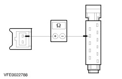
Check the multi-function switch Multi-function switch, connection point for connector C65b 1. Check the OFF function Check the multi-function switch NOTE:All of the specified pins are located on the connection point for connector C65b (see illustration). - Set the wiper lever to OFF.
- Measure the resistance between pin 3 and pin 4. The required value is less than 2 Ohm.
- Measure the resistance between pin 5 and pin 10. The required value is more than 10 kOhm.
- Measure the resistance between pin 9 and pin 10. The required value is more than 10 kOhm.
If the measured values are not as specified, RENEW the multi-function switch; otherwise go to 2. 2. Check INTERMITTENT function Check the multi-function switch NOTE:All of the specified pins are located on the connection point for connector C65b (see illustration). - Set the wiper lever to INTERMITTENT WIPE.
- Measure the resistance between pin 9 and pin 10. The required value is less than 2 Ohm.
- Measure the resistance between pin 4 and pin 8. The required value is less than 2 Ohm.
- Measure the resistance between pin 4 and pin 10. The required value is more than 10 kOhm.
If the measured values are not as specified, RENEW the multi-function switch; otherwise go to 3. 3. Check the SLOW WIPE function. Check the multi-function switch NOTE:All of the specified pins are located on the connection point for connector C65b (see illustration). - Move the wiper lever to SLOW WIPE.
- Measure the resistance between pin 4 and pin 10. The required value is less than 2 Ohm.
- Measure the resistance between pin 4 and pin 8. The required value is more than 10 kOhm.
- Measure the resistance between pin 9 and pin 10. The required value is more than 10 kOhm.
If the measured values are not as specified, RENEW the multi-function switch; otherwise go to 4. 4. Check the FAST WIPE function Check the multi-function switch NOTE:All of the specified pins are located on the connection point for connector C65b (see illustration). - Move the wiper lever to FAST WIPE.
- Measure the resistance between pin 5 and pin 10. The required value is less than 2 Ohm.
- Measure the resistance between pin 4 and pin 8. The required value is more than 10 kOhm.
- Measure the resistance between pin 9 and pin 10. The required value is more than 10 kOhm.
If the measured values are not as specified, RENEW the multi-function switch; otherwise go to 5. 5. Check REAR WINDOW WIPE function Check the multi-function switch Multi-function switch - connection point for connector C65a NOTE:Pin L8 means pin 8 on connection point for connector C65a (see illustration). All of the other pins are located on the connection point for connector C65b (see illustration under step 1). - Set the wiper lever to OFF.
- Measure the resistance between pin 7 and pin L8. The required value is less than 2 Ohm.
- Measure the resistance between pin 7 and pin 10. The required value is more than 10 kOhm.
- Measure the resistance between pin 2 and pin 10. The required value is less than 2 Ohm.
- Switch the wiper lever to REAR WIPER ON.
- Measure the resistance between pin 2 and pin 10. The required value is less than 2 Ohm.
- Measure the resistance between pin 7 and pin 10. The required value is less than 2 Ohm.
- Measure the resistance between pin 7 and pin L8. The required value is more than 10 kOhm.
If the measured values are not as specified, RENEW the multi-function switch; otherwise go to 6. 6. Check WINDSHIELD WASH/WIPE function Check the multi-function switch NOTE:Pin L8 means pin 8 on connection point for connector C65a (see illustration). All of the other pins are located on the connection point for connector C65b (see illustration under step 1). NOTE:The circuit is switched to "OFF" if there is a resistance of less than 2 Ohm between pin 1 and pin 10, and a resistance of more than 10 kOhm between pin 1and pin L8. NOTE:At all stages of the test the resistance will change from less than 2 Ohm to more than 10 kOhm and vice versa, each time the switch is pressed. - Set the wiper lever to OFF.
- Measure the resistance between pin 1 and pin 10. The required value is less than 2 Ohm.
- Measure the resistance between pin 1 and pin L8. The required value is more than 10 kOhm.
- Switch the wiper lever to WINDSHIELD WASH/WIPE.
- Measure the resistance between pin 1 and pin 10. The required value is more than 10 kOhm.
- Measure the resistance between pin 1 and pin L8. The required value is less than 2 Ohm.
If the measured values are not as specified, RENEW the multi-function switch; otherwise go to 7. 7. Check REAR WASH/WIPE function Check the multi-function switch NOTE:Pin L8 means pin 8 on connection point for connector C65a (see illustration). All of the other pins are located on the connection point for connector C65b (see illustration under step 1). - Set the wiper lever to OFF.
- Measure the resistance between pin 2 and pin 10. The required value is less than 2 Ohm.
- Measure the resistance between pin 7 and pin L8. The required value is less than 2 Ohm.
- Switch the wiper lever to REAR WASH/WIPE and hold it there.
- Measure the resistance between pin 2 and pin 10. The required value is more than 10 kOhm.
- Measure the resistance between pin 7 and pin L8. The required value is more than 10 kOhm.
If the specified values are achieved then the multi-function switch is OK, otherwise RENEW the multi-function switch. |