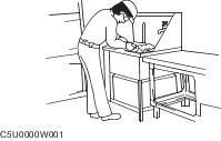
| Description and Operation Range of Topics This manual contains procedures for performing all required service operations. The procedures are divided into the following five basic operations: - Removal/Installation
- Disassembly/Assembly
- Replacement
- Inspection
- Adjustment
Simple operations which can be performed easily just by looking at the vehicle (i.e., removal/installation of parts, jacking, vehicle lifting, cleaning of parts, and visual inspection) have been omitted. Service Procedure Inspection, adjustment Inspection and adjustment procedures are divided into steps. Important points regarding the location and contents of the procedures are explained in detail and shown in the illustrations. Repair procedure 1. Most repair operations begin with an overview illustration. It identifies the components, shows how the parts fit together, and describes visual part inspection. However, only removal/installation procedures that need to be performed methodically have written instructions. 2. Expendable parts, tightening torques, and symbols for oil, grease, and sealant are shown in the overview illustration. In addition, symbols indicating parts requiring the use of special service tools or equivalent are also shown. 3. Procedure steps are numbered and the part that is the main point of that procedure is shown in the illustration with the corresponding number. Occasionally, there are important points or additional information concerning a procedure. Refer to this information when servicing the related part. Symbols There are eight symbols indicating oil, grease, fluids, sealant, and the use of SST or equivalent. These symbols show application points or use of these materials during service. - Apply oil. New appropriate engine oil or gear oil.
- Apply brake fluid. New appropriate brake fluid.
- Apply automatic transaxle/transmission fluid. New appropriate automatic transaxle/transmission fluid.
- Apply grease. Appropriate grease.
- Apply sealant. Appropriate sealant.
- Apply petroleum jelly. Appropriate petroleum jelly.
- Replace part. O-ring, gasket, etc.
- Use SST or equivalent. Appropriate tools.
Advisory Messages You will find several Warnings, Cautions, Notes, Specifications and Upper and Lower Limits in this manual. Warning A Warning indicates a situation in which serious injury or death could result if the warning is ignored. Caution A Caution indicates a situation in which damage to the vehicle or parts could result if the caution is ignored. Note A Note provides added information that will help you to complete a particular procedure. Specification The values indicate the allowable range when performing inspections or adjustments. Upper and lower limits The values indicate the upper and lower limits that must not be exceeded when performing inspections or adjustments. Troubleshooting Procedure Basic flow of troubleshooting DTC troubleshooting flow (on-board diagnostic) Diagnostic trouble codes (DTCs) are important hints for repairing malfunctions that are difficult to simulate. Perform the specific DTC diagnostic inspection to quickly and accurately diagnose the malfunction. The on-board diagnostic function is used during inspection. When a DTC is shown specifying the cause of a malfunction, continue the diagnostic inspection according to the items indicated by the on-board diagnostic function. Diagnostic index The diagnostic index lists the symptoms of specific malfunctions. Select the symptoms related or most closely relating to the malfunction. Quick diagnosis chart (If mentioned) The quick diagnosis chart lists diagnosis and inspection procedures to be performed specifically relating to the cause of the malfunction. Symptom troubleshooting Symptom troubleshooting quickly determines the location of the malfunction according to symptom type. Procedures for UseUsing the basic inspection (section 05) Perform the basic inspection procedure before symptom troubleshooting. Perform each step in the order shown. The reference column lists the location of the detailed procedure for each basic inspection. Although inspections and adjustments are performed according to the reference column procedures, if the cause of the malfunction is discovered during basic inspection, continue the procedures as indicated in the action column. Using the DTC troubleshooting flow DTC troubleshooting flow shows diagnostic procedures, inspection methods, and proper action to take for each DTC. Using the diagnostic index Malfunction symptoms are listed in the diagnostic index under symptom troubleshooting. The exact malfunction symptoms can be selected by following the index. Using the quick diagnosis chart The chart lists the relation between the symptom and the cause of the malfunction. The chart is effective in quickly narrowing down the relation between symptom and cause of the malfunction. It also specifies a range of common causes when multiple malfunction symptoms occur. The appropriate diagnostic inspection relating to a malfunction cause as specified by the symptoms can be selected by looking down the diagnostic inspection column of the chart. Using the symptom troubleshooting Symptom troubleshooting shows diagnostic procedures, inspection methods, and proper action to be taken for each trouble symptom. Units | Description | Unit | | Electric current | A (ampere) | | Electric power | W (watt) | | Electric resistance | ohm | | Electric voltage | V (volt) | | Length | mm (millimeter) | | in (inch) | | Negative pressure | kPa (kilo pascal) | | mmHg (millimeters of mercury) | | inHg (inches of mercury) | | Positive pressure | kPa (kilo pascal) | | kgf/cm2(kilogram force per square centimeter | | psi (pounds per square inch) | | Number of revolutions | rpm (revolutions per minute) | | Torque | Nm (Newton meter) | | kgf·m (kilogram force meter) | | kgf·cm (kilogram force centimeter) | | ft·lbf (foot pound force) | | in·lbf (inch pound force) | | Volume | L (liter) | | US qt (U.S. quart) | | cc (cubic centimeter) | | Imp qt (Imperial quart) | | ml (milliliter) | | cu in (cubic inch) | | fl oz (fluid ounce) | | Weight | g (gram) | | oz (ounce) | Conversion to SI Units (Système International d’Unités) All numerical values in this manual are based on SI units. Numbers shown in conventional units are converted from these values. Rounding Off Converted values are rounded off to the same number of places as the SI unit value. For example, if the SI unit value is 17.2 and the value after conversion is 37.84, the converted value will be rounded off to 37.8. Upper and Lower Limits When the data indicates upper and lower limits, the converted values are rounded down if the SI unit value is an upper limit, and rounded up if the SI unit value is a lower limit. Therefore, converted values for the same SI unit value may differ after conversion. For example, consider 2.7 kgf/cm2 in the following specifications: - 210—260 kPa {2.1—2.7 kgf/cm2, 30—38 psi}
- 270—310 kPa {2.7—3.2 kgf/cm2, 39—45 psi}
The actual converted values for 2.7 kgf/cm2are 265 kPa and 38.4 psi. In the first specification, 2.7 is used as an upper limit, so the converted values are rounded down to 260 and 38. In the second specification, 2.7 is used as a lower limit, so the converted values are rounded up to 270 and 39. SERVICE CAUTIONS Protection of the Vehicle Always be sure to cover fenders, seats and floor areas before starting work. Preparation of Tools and Measuring Equipment Be sure that all necessary tools and measuring equipment are available before starting any work. Special Service Tools Use special service tools or the equivalent when they are required. Disconnection of the Negative Battery Cable Before beginning any work, turn the ignition switch to the LOCK position, then disconnect the negative battery cable and wait for more than 1 min. to allow the backup power supply of the SAS control module to deplete its stored power. Disconnecting the battery cable will delete the memories of the clock, audio, and DTCs, etc. Therefore, it is necessary to note down the information stored in those memories before disconnecting the cable. If the battery had been disconnected during vehicle maintenance or for other reasons, the window will not fully close automatically. Initialize the power window system for the power window main switch.
For additional information, refer to: Door Window Motor Initialization (501-11 Glass, Frames and Mechanisms, General Procedures).
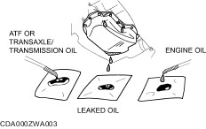
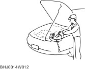
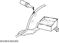
Oil Leakage Inspection Use either of the following procedures to identify the type of oil that is leaking. Using UV light (black light) 1. Remove any oil on the engine or transaxle/transmission. NOTE:Referring to the fluorescent dye instruction manual, mix the specified amount of dye into the engine oil or ATF (or transaxle/transmission oil). 2. Pour the fluorescent dye into the engine oil or ATF (or transaxle/transmission oil). 3. Allow the engine to run for 30 min. 4. Inspect for dye leakage by irradiating with UV light (black light), and identify the type of oil that is leaking. 5. If no dye leakage is found, allow the engine to run for another 30 min. or drive the vehicle then reinspect. 6. Find where the oil is leaking from, then make necessary repairs. NOTE:To determine whether it is necessary to replace the oil after adding the fluorescent dye, refer to the fluorescent dye instruction manual. Not using UV light (black light) 1. Gather some of the leaking oil using an absorbent white tissue 2. Take samples of engine oil and ATF (or transaxle/transmission oil), both from the dipstick, and place them next to the leaked oil already on the tissue. 3. Compare the appearance and smell, and identify the type of oil that is leaking. 4. Remove any oil on the engine or transaxle/transmission. 5. Allow the engine to run for 30 min. 6. Check the area where the oil is leaking, then make necessary repairs. Removal of Parts While correcting a problem, also try to determine its cause. Begin work only after first learning which parts and sub-components must be removed and disassembled for replacement or repair. After removing the part, plug all holes and ports to prevent foreign material from entering. Disassembly If the disassembly procedure is complex, requiring many parts to be disassembled, all parts should be marked in a place that will not affect their performance or external appearance, and identified so that reassembly can be performed easily and efficiently. Inspection During Removal, Disassembly When removed, each part should be carefully inspected for malfunction, deformation, damage and other problems. Arrangement of Parts All disassembled parts should be carefully arranged for reassembly. Be sure to separate or otherwise identify the parts to be replaced from those that will be reused. Cleaning of Parts All parts to be reused should be carefully and thoroughly cleaned in the appropriate method. WARNING:Using compressed air can cause dirt and other particles to fly out causing injury to the eyes. Wear protective eye wear whenever using compressed air. Reassembly Standard values, such as torques and certain adjustments, must be strictly observed in the reassembly of all parts. If removed, these parts should be replaced with new ones: - Oil seals
- Gaskets
- O-rings
- Lock washers
- Cotter pins
- Nylon nuts
Depending on location: - Sealant and gaskets, or both, should be applied to specified locations. When sealant is applied, parts should be installed before sealant hardens to prevent leakage.
- Oil should be applied to the moving components of parts.
- Specified oil or grease should be applied at the prescribed locations (such as oil seals) before reassembly.
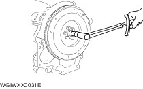
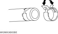
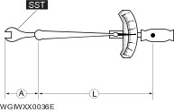
Adjustment Use suitable gauges and testers when making adjustments. Rubber Parts and Tubing Prevent gasoline or oil from getting on rubber parts or tubing. Hose Clamps When reinstalling, position the hose clamp in the original location on the hose and squeeze the clamp lightly with large pliers to ensure a good fit. Torque Formulas When using a torque wrench-SST or equivalent combination, the specified torque must be recalculated due to the extra length that the SST or equivalent adds to the torque wrench. Recalculate the torque by using the following formulas. Choose the formula that applies to you. | Torque Unit | Formula | | Nm | Nm ×[L/(L+A)] | | kgf·m | kgf·m ×[L/(L+A)] | | kgf·cm | kgf·cm ×[L/(L+A)] | | ft·lbf | ft·lbf ×[L/(L+A)] | | in·lbf | in·lbf ×[L/(L+A)] | - A : The length of the SST past the torque wrench drive.
- L : The length of the torque wrench.
Vise When using a vise, put protective plates in the jaws of the vise to prevent damage to parts. Dynamometer When inspecting and servicing the power train on the dynamometer or speedometer tester, pay attention to the following: - Place a fan, preferably a vehicle-speed proportional type, in front of the vehicle.
- Make sure the vehicle is in a facility with an exhaust gas ventilation system.
- Since the rear bumper might deform from the heat, cool the rear with a fan. (Surface of the bumper must be below 70°C {158°F} degrees.)
- Keep the area around the vehicle uncluttered so that heat does not build up.
- Watch the water temperature gauge and do not overheat the engine
- Avoid added load to the engine and maintain normal driving conditions as much as possible.
When only the front or rear wheels are rotated on a chassis dynamometer or equivalent, the ABS CM determines that there is a malfunction in the ABS and illuminates the following lights: - ABS warning light
- Brake system warning light
If the above lights are illuminated, dismount the vehicle from the chassis dynamometer and turn the ignition switch to the LOCK position. Then, turn the ignition switch back to the ON position, run the vehicle at 10 km/h or more and verify that the warning lights go out. In this case, a DTC will be stored in the memory. Clear the DTC from the memory by following the memory clearing procedure [ABS] in the on-board diagnostic system. 4WD inspection/service Speedometer tester measurement CAUTION:Install the tension bar (chain wire) to the tie down hook and secure the vehicle to prevent it from rolling and running off. CAUTION:Do not accelerate suddenly from a standstill or accelerate/decelerate rapidly. Free roller type 1. Align the free rollers with the wheel base and tread, then set them on the floor properly. 2. Drive the vehicle slowly onto the tester roller and free rollers. 3. Start the engine and accelerate gradually to inspect the speedometer. 4. After inspection, decelerate gradually with gentle braking. Propeller shaft removal type 1. Remove the propeller shaft. 2. Place the front wheels on the tester roller. 3. Accelerate gradually and inspect the speedometer. After inspection, decelerate gradually with gentle braking. Install the propeller shaft. Brake tester measurement 1. Place the wheels (front or rear) to be measured on the tester roller. 2. Shift to the N position/neutral. 3. Activate the tester roller and measure braking force. If there is a large amount of brake drag force, the electronic control system coupling may be affected. Jack up all four wheels to eliminate the effect of the coupling and rotate each wheel by hand to verify the rotation condition. Wheel balancer (on the vehicle balancer) 1. Jack up all four wheels. 2. Support the wheels (front or rear) on the side to be measured (near the wheels) using a wheel balancer sensor stand. 3. Support the wheels on the side not to be measured (near the wheels) using safety stands. 4. Set up the wheel balancer and rotate the wheels using engine drive to measure the wheel balance. SST Some global SST or equivalent are used as SSTs necessary for vehicle repair. Note that these SSTs are marked with global SST numbers. Note that a global SST number is written together with a corresponding Mazda SST number as shown below. Example (SERVICE TOOLS) | Number | Description | | 1: Mazda SST number | 1: 49 UN303 009 | | 2: Global SST number | 2: 303-009 | | | Crankshaft Damper Remover | | | | INSTALLATION OF RADIO SYSTEM If a radio system is installed improperly or if a high-powered type system is used, the CIS and other systems may be affected. When the vehicle is to be equipped with a radio, observe the following precautions: - Install the antenna at the farthest point from control modules.
- Install the antenna feeder as far as possible from the control module wiring harnesses.
- Ensure that the antenna and feeder are properly adjusted.
- Do not install a high-powered radio system.
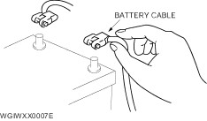
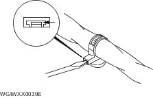
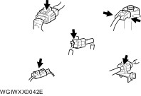
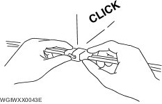
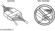
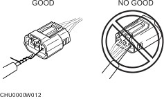
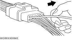
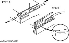
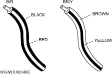
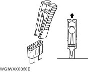
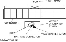
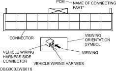
ELECTRICAL SYSTEM Battery cable Before disconnecting connectors or removing electrical parts, disconnect the negative battery cable. Wiring Harness To remove the wiring harness from the clip in the engine room, pry up the hook of the clip using a flathead screwdriver. CAUTION:Do not remove the wiring harness protective tape. Otherwise, the wires could rub against the body, which could result in water penetration and electrical shorting. Disconnecting connectors When disconnecting a connector, grasp the connectors, not the wires. Connectors can be disconnected by pressing or pulling the lock lever as shown. Locking connector When locking connectors, listen for a click indicating they are securely locked. Inspection When a tester is used to inspect for continuity or measuring voltage, insert the tester probe from the wiring harness side. Inspect the terminals of water proof connectors from the connector side since they cannot be accessed from the wiring harness side. CAUTION:To prevent damage to the terminal, wrap a thin wire around the tester probe before inserting into terminal. Terminals Inspection Pull lightly on individual wires to verify that they are secured in the terminal. Replacement Use the appropriate tools to remove a terminal as shown. When installing a terminal, be sure to insert it until it locks securely. Insert a thin piece of metal from the terminal side of the connector and with the terminal locking tab pressed down, pull the terminal out from the connector. Sensors, Switches, and Relays Handle sensors, switches, and relays carefully. Do not drop them or strike them against other objects. Wiring Harness Wiring color codes Two-color wires are indicated by a two-color code symbol. The first letter indicates the base color of the wire and the second is the color of the stripe. | CODE | COLOR | CODE | COLOR | | B | Black | O | Orange | | BR | Brown | P | Pink | | G | Green | R | Red | | GY | Gray | V | Violet | | L | Blue | W | White | | LB | Light Blue | Y | Yellow | | LG | Light Green | | | Fuse Replacement When replacing a fuse, be sure to replace it with one of the same capacity. If a fuse malfunctions again, the circuit probably has a short and the wiring should be inspected. Be sure the negative battery terminal is disconnected before replacing a main fuse. When replacing a pullout fuse, use the fuse puller. Viewing Orientation for Connectors The viewing orientation for connectors is indicated with a symbol. The figures showing the viewing orientation are the same as those used in Wiring Diagrams. The viewing orientations are shown in the following three ways. Part-side connector The viewing orientation for part-side connectors is from the terminal side. NOTE:Part names are shown only when there are multiple connector drawings. Vehicle harness-side connector The viewing orientation for vehicle wiring harness-side connectors is from the wiring harness side. NOTE:Part names are shown only when there are multiple connector drawings. Other When it is necessary to show the terminal side of the vehicle wiring harness-side connectors, such as the following connectors, the viewing orientation is from the terminal side. - Main fuse block and the main fuse block relays.
- Data link connector.
- Check connector.
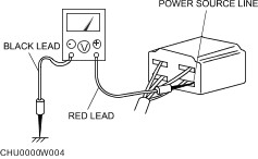
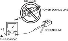
- Relay box.
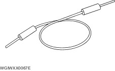
Electrical Troubleshooting Tools Jumper wire A jumper wire is used to create a temporary circuit. Connect the jumper wire between the terminals of a circuit to bypass a switch. CAUTION:Do not connect a jumper wire from the power source line to a body ground. This may cause burning or other damage to wiring harnesses or electronic components. Voltmeter The DC voltmeter is used to measure circuit voltage. A voltmeter with a range of 15 V or more is used by connecting the positive (+) probe (red lead wire) to the point where voltage will be measured and the negative (-) probe (black lead wire) to a body ground. Ohmmeter The ohmmeter is used to measure the resistance between two points in a circuit and to inspect for continuity and short circuits. CAUTION:Do not connect the ohmmeter to any circuit where voltage is applied. This will damage the ohmmeter. Precautions Before Welding A vehicle has various electrical parts. To protect the parts from excessive current generated when welding, be sure to perform the following procedure. - Turn the ignition switch to the LOCK position.
- Disconnect the battery cables.
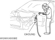
- Securely connect the welding machine ground near the welding area.
- Cover the peripheral parts of the welding area to protect them from weld spatter.
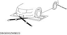
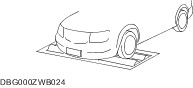
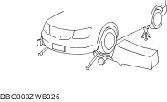
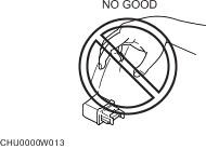
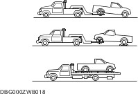
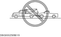
TOWING Proper lifting and towing are necessary to prevent damage to the vehicle. Particularly when towing a 4WD vehicle, where all the wheels are connected to the drive train, proper transporting of the vehicle is absolutely essential to avoid damaging the drive system. Government and local laws must be followed. A towed vehicle usually should have its rear wheels off the ground. If excessive damage or other conditions prevent this, use wheel dollies. CAUTION:Do not tow with sling-type equipment. This could damage the vehicle. Use wheel-lift or flatbed equipment. CAUTION: Follow these instructions when towing the vehicle with all wheels on the ground or with the front wheels on the ground and the rear wheels raised. - Shift to neutral.
- Turn the ignition switch to the ACC position.
- Release the parking brake.
CAUTION:Remember that power assist for the brakes and steering will not be available when the engine is not running. If the transmission, 4WD system, rear axle, and steering system are not damaged, the vehicle may be towed on all four wheels. If any of these components are damaged, use wheel dollies or flatbed equipment. CAUTION:Follow these instructions when towing the 4WD vehicle with all wheels on the ground or with the front wheels on the ground and the rear wheels raised. - Put the transfer shift lever in 2H.
- Set the remote free-wheel system to FREE mode.
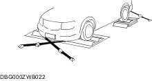
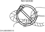
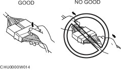
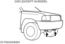
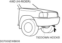
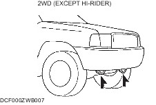
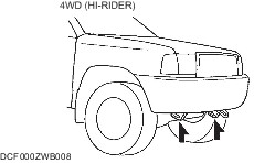
CAUTION:Remember that power assist for the brakes and steering will not be available when the engine is not running. If towing service is not available in an emergency, the vehicle may be towed with all four wheels on the ground using the towing hook at the front of the vehicle. Only tow the vehicle on paved surfaces for short distances at low speeds. Towing/Tiedown Hooks CAUTION:The towing hook should be used in an emergency (to get the vehicle out of a ditch for example). CAUTION:When using the towing hooks, always pull the cable or chain in a straight direction with respect to the hook. Apply no sideways force. CAUTION:Don’t use the tiedown hooks under the front for towing. They are designed ONLY for tying down the vehicle when it’s for towing will damage the bumper. NOTE:When towing with chain or cable, wrap the chain or cable with a soft cloth near the bumper to prevent damage to the bumper. Towing Hooks Tiedown Hooks CAUTION:Do not use the hook loops under the front for towing. They are designed ONLY for tying down the vehicle when it is being transported. Using them for towing will damage the bumper. IDENTIFICATION NUMBER LOCATIONS Vehicle Identification Number (VIN) Engine Identification Number NEW STANDARDS Following is a comparison of the previous standard and the new standard. | New Standard | Previous Standard | Remark | | Abbreviation | Name | Abbreviation | Name | | AP | Accelerator Pedal | — | Accelerator Pedal | | | APP | Accelerator Pedal Position | — | Accelerator Pedal Position | | | ACL | Air Cleaner | — | Air Cleaner | | | A/C | Air Conditioning | — | Air Conditioning | | | BARO | Barometric Pressure | — | Barometric Pressure | | | B+ | Battery Positive Voltage | VB | Battery Voltage | | | — | Brake Switch | — | Stoplight Switch | | | — | Calibration Resistor | — | Corrected Resistance | 6 | | CMP | sensor Camshaft Position Sensor | — | Crank Angle Sensor | | | LOAD | Calculated Load Voltage | — | — | | | CAC | Charge Air Cooler | — | Intercooler | | | CLS | Closed Loop System | — | Feedback System | | | CTP | Clutch Pedal Position | — | Fully Closed | | | CPP | Clutch Pedal Position | — | Clutch Position | | | CIS | Continuous Fuel Injection System | EGI | Electronic Gasoline Injection System | | | CS sensor | Control Sleeve Sensor | CSP sensor | Control Sleeve Position Sensor | 6 | | CKP sensor | Crankshaft Position Sensor | — | Crank Angle Sensor 2 | | | DLC | Data Link Connector | — | Diagnosis Connector | | | DTM | Diagnostic Test Mode | — | Test Mode | 1 | | DTC | Diagnostic Trouble Code(s) | — | Service Code(s) | | | DI | Distributor Ignition | — | Spark Ignition | | | DLI | Distributorless Ignition | — | Direct Ignition | | | EI | Electronic Ignition | — | Electronic Spark Ignition | 2 | | ECT | Engine Coolant Temperature | — | Water Thermo | | | EM | Engine Modification | — | Engine Modification | | | — | Engine Speed Input Signal | — | Engine RPM Signal | | | EVAP | Evaporative Emission | — | Evaporative Emission | | | EGR | Exhaust Gas Recirculation | — | Exhaust Gas Recirculation | | | FC | Fan Control | — | Fan Control | | | FF | Flexible Fuel | — | Flexible Fuel | | | 4GR | Fourth Gear | — | Circuit Opening Relay | | | FSO solenoid | Fuel Shut Off Solenoid | FCV | Fuel Cut Valve | 6 | | GEN | Generator | — | Alternator | | | GND | Ground | — | Ground/Earth | | | HO2S | Heated Oxygen Sensor | — | Oxygen Sensor | With heater | | IAC | Idle Air Control | — | Idle Speed Control | | | — | IDM Relay | — | Spill Valve Relay | 6 | | — | Incorrect Gear Ratio | — | — | | | — | Injection Pump | — | Fuel Injection Pump | 6 | | — | Input/Turbine Speed Sensor | — | Pulse Generator | | | IAT | Intake Air Temperature | — | Intake Air Thermo | | | KS | Knock Sensor | — | Knock Sensor | | | MIL | Malfunction Indicator Lamp | — | Malfunction Indicator Lamp | | | MAP | Manifold Absolute Pressure | — | Intake Air Pressure | | | MAF | Mass Air Flow | — | Mass Air Flow | | | MAF sensor | Mass Air Flow Sensor | — | Airflow Sensor | | | MFL | Multiport Fuel Injection | — | Multiport Fuel Injection | | | OBD | On-Board Diagnostic | — | Diagnosis/Self Diagnosis | | | OL | Open Loop | — | Open Loop | | | — | Output Speed Sensor | — | Vehicle Speed Sensor 1 | | | OC | Oxidation Catalytic Converter | — | Catalytic Converter | | | O2S | Oxygen Sensor | — | Oxygen Sensor | | | PNP | Park/Neutral Position | — | Park/Neutral Position | | | PID | Parameter Identification | — | Parameter Identification | | | — | PCM Control Relay | — | Main Relay | 6 | | PSP | Power Steering Pressure | — | Power Steering Pressure | | | PCM | Powertrain Control Module | ECU | Engine Control Unit | 4 | | — | Pressure Control Solenoid | — | Line Pressure Solenoid Valve | | | PAIR | Pulsed Secondary Air Injection | — | Secondary Air Injection System | Pulsed injection | | — | Pump Speed Sensor | — | NE Sensor | 6 | | RAM | Random Access Memory | — | — | | | AIR | Secondary Air Injection | — | Secondary Air Injection System | Injection with air pump | | SAPV | Secondary Air Pulse Valve | — | Reed Valve | | | SFI | Sequential Multipoint Fuel Injection | — | Sequential Fuel Injection | | | — | Shift Solenoid A | — | 1–2 Shift Solenoid Valve | | | — | Shift A Solenoid Valve | | | — | Shift Solenoid B | — | 2–3 Shift Solenoid Valve | | | — | Shift B Solenoid Valve | | | — | Shift Solenoid C | — | 3–4 Shift Solenoid Valve | | | 3GR | Third Gear | — | 3rd Gear | | | TWC | Three Way Catalytic Converter | — | Catalytic Converter | | | TB | Throttle Body | — | Throttle Body | | | TP | Throttle Position | — | | | | TP sensor | Throttle Position Sensor | — | Throttle Sensor | | | TCV | Timer Control Valve | TCV | Timing Control Valve | 6 | | TCC | Torque Converter Clutch | — | Lockup Position | | | TCM | Transmission (Transaxle) Control Module | — | EC-AT Control Unit | | | — | Transmission (Transaxle) Fluid Temperature Sensor | — | ATF Thermosensor | | | TR | Transmission (Transaxle) Range | — | Inhibitor Position | | | TC | Turbocharger | — | Turbocharger | | | VSS | Vehicle Speed Sensor | — | Vehicle Speed Sensor | | | VR | Voltage Regulator | — | IC Regulator | | | VAF sensor | Volume Air Flow Sensor | — | Air Flow Sensor | | | WUTWC | Warm Up Three Way Catalytic Converter | — | Catalytic Converter | 5 | | WOT | Wide Open Throttle | — | Fully Open | | - Diagnostic trouble codes depend on the diagnostic test mode.
- Controlled by the PCM.
- In some models, there is a fuel pump relay that controls pump speed. That relay is now called the fuel pump relay (speed).
- Device that controls engine and powertrain.
- Directly connected to exhaust manifold.
- Part name of diesel engine.
| | | | ABS | Antilock Brake System | | ATDC | After Top Dead Center | | ATF | Automatic Transmission Fluid | | BTDC | Before Top Dead Center | | CM | Control Module | | ELR | Emergency Locking Retractor | | EX | Exhaust | | HI | High | | HU | Hydraulic Unit | | IDS | Integrated Diagnostic Software | | IN | Intake | | INT | Intermittent | | KOEO | Key On Engine Off | | KOER | Key On Engine Running | | LCD | Liquid Crystal Display | | LED | Light Emitting Diode | | LF | Left Front | | LH | Left Hand | | LO | Low | | LR | Left Rear | | LSD | Limited Slip Differential | | LSPV | Load Sensing Proportioning Valve | | M | Motor | | MAX | Maximum | | MIN | Minimum | | PDS | Portable Diagnostic Software | | PID | Parameter Identification | | P/S | Power Steering | | P/W | Power Window | | RF | Right Front | | RFW | Remote Freewheel | | RH | Right Hand | | RR | Right Rear | | SAS | Sophisticated Air Bag Sensor | | SST | Special Service Tool | | SW | Switch | | TDC | Top Dead Center | | TNS | Tail Number Side Lights | | VBC | Variable Boost Control | | VENT | Ventilation | | WDS | Worldwide Diagnostic System | | 4W-ABS | 4-Wheel Antilock Brake System | | 4×2 | 4-wheel 2-drive | | 4×4 | 4-wheel 4-drive | |