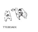
| Removal and Installation Special Tool(s) | | Ball Joint Puller Set 49 T028 3A0 | | | Lower Arm Bushing Puller & Installer Set 49 U034 2A0 | | | -
Remove the ABS sensor wiring harness brackets installed to the upper arm and steering knuckle, then move aside the ABS sensor. | 2. Remove the components in the order indicated in the following illustration(s) and table(s). 4 - Shock absorber lower bolt and nut 8 - Torsion bar spring component 12 - Lower arm spindle (rear), washer and nut 13 - Lower arm spindle (front), washer and nut 17 - Front lower arm ball joint 3. To install, reverse the removal procedure. | | -
Inspect the vehicle height and adjust it as necessary.
For additional information, refer to: Ride Height Adjustment (204-00 Suspension System - General Information, General Procedures).
| | | -
Inspect the front wheel alignment as necessary.
For additional information, refer to: Front Toe Adjustment (204-00 Suspension System - General Information, General Procedures).
| Removal Details Item 3 : Front lower arm ball joint | | -
Separate the ball joint from the knuckle arm using the SST. | Item 9 : Anchor arm | | -
Mark the anchor arm and body for reference during installation. | Item 10 : Torsion bar spring | | -
Mark the torsion bar spring and anchor arm, and torsion bar spring and torque plate for reference during installation. | Item 20 : Front lower arm bushing | | -
Remove the front lower arm bushing using the SST. | Installation Details Item 20 : Front lower arm bushing | | -
Apply soapy water to the new bushing. | | | -
Install the bushing using the SST. | Item 10 : Torsion bar spring | | -
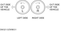
Before installation, check the identification mark on the end of the torsion bar spring. | | | -
Align the marks made during removal, and connect the torsion bar spring to the torque plate. | Item 9 : Anchor arm | | -
Align the marks made during removal, and install the anchor arm onto the torsion bar spring. | Item 5 : Anchor bolt | | -
NOTE:If the anchor bolt was not marked during removal, install it as follows: - Lower the front suspension until the upper arm contacts the rebound stopper.
Install the anchor bolt, and tighten it until the marks made during removal are aligned. | | | -
Install the anchor arm so that the angle A is 55°30'—64°30'. | |