| Removal and Installation Special Tool(s) | | Sensor Rotor Installer 49 D026 102 | | | Wheel Hub Puller SST 49 F026 103 | | | Attachment 49 F027 009 | | | Bearing Installer SST 49 G019 011 | | | Handle 49 G030 797 | | | Handle 49 G033 102 | | | Oil Seal Installer 49 S033 106 | | | Oil Seal Installer 49 S033 107 | | | Ball Joint Puller Set 49 T028 3A0 | | | Oil Seal Installer W010 107A | CAUTION:Performing the following procedures without first removing the ABS wheel-speed sensor may possibly cause an open circuit in the harness if it is pulled by mistake. Before performing the following procedures, remove the ABS wheel-speed sensor (axle side) and fix it to an appropriate place where the sensor will not be pulled by mistake while the vehicle is being serviced. 1. Remove the components in the order indicated in the following illustration(s) and table(s). 1 - ABS wheel-speed sensor (with ABS) 12 - Wheel hub, steering knuckle, dust cover 14 - ABS sensor rotor (with ABS) or spacer (without ABS) 2. To install, reverse the removal procedure. Removal Details Item 3 : Locknut | | -
NOTE:Remove the locknut with the vehicle on level ground. Knock the crimped portion of the locknut outward using a small chisel and a hammer. | Item 5 : Brake caliper component | | -
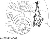
Remove the brake caliper component, and suspend it with rope. | Item 7 : Tie-rod end ball joint | | -
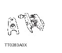
Separate the tie-rod end from the steering knuckle using the SSTs. | Item 8 : Bolt (stabilizer) | | -
For additional information, refer to: Stabilizer Bar - 4x4 (204-01 Front Suspension, Removal and Installation). | Item 11 : Lower arm ball joint | | -
For additional information, refer to: Lower Arm - 4x4 (204-01 Front Suspension, Removal and Installation). | Item 13 : Wheel hub component | | -
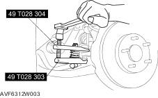
Remove the wheel hub component using the SSTs and a press. | | | -
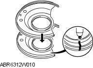
If the bearing inner race remains on the front wheel hub component, grind a section of the bearing inner race until approx. 0.5 mm {0.02 in} remains. Then remove it using a chisel. | Item 16 : Wheel bearing | | -
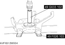
Remove the wheel bearing using the SSTs and a press. | Item 17 : Dust cover | | -
NOTE:The dust cover does not need to be removed unless it is being replaced. Mark the dust cover and steering knuckle for proper installation. | | | -
Remove the dust cover using a chisel. | Item 19 : Hub bolt | | -
NOTE:The hub bolts do not need to be removed unless they are being replaced. Remove the hub bolts using a press. | Installation Details Item 19 : Hub bolt | | -
Install the new hub bolts using a press. | Item 17 : Dust cover | | -
Mark the new dust cover in the same way as the removed one. | | -
Align the marks of the new dust cover and the knuckle. | | | -
Install the new dust cover using the SSTs and a press. | Item 16 : Wheel bearing | | -
Install the new wheel bearing using the SSTs and a press. | Item 13 : Wheel hub component | | -
Install the wheel hub component using the SSTs and a press. | Item 3 : Locknut | | -
NOTE:Install the locknut with the vehicle on level ground. Install a new locknut and stake it as shown. | |