| Disassembly and Assembly Special Tool(s) | | Engine Stand 49 0107 680A | | | Side Bearing Adjustment Wrench 49 0259 720 | | | Gauge Block 49 0600 555 | | | Gauge Block 49 0660 555 | | | Pinion Height Gauge Body 49 0727 570 | | | Bearing Puller Set 49 0839 425C | | | Drive Pinion Model 49 8531 565 | | | Collar A 49 8531 567 | | | Collar B 49 8531 568 | | | Attachment for ø 80 49 F027 004 | | | Attachment for ø 72 49 F027 007 | | | Oil Seal Installer 49 U027 009 | | | Body 49 F401 331 | | | Attachment C 49 F401 337A | | | Oil Seal Installer 49 G030 796 | | | Handle 49 G030 797 | | | Bearing Remover 49 H027 002 | | | Differential Carrier Hanger 49 M005 561 | | | Coupling Flange Holder 49 S120 710 | | | Bearing Installer 49 UB71 525 | 1. Disassemble the components in the order indicated in the following illustration(s) and table(s). 8 - Side bearing outer race 14 - Front bearing inner race 2. Assemble the components in the order indicated in the following illustration(s) and table(s). 18 - Front bearing inner race Disassembly Details Item 4 : Differential component | | -
Install the differential component to the SSTs. | Item 6 : Bearing cap | | -
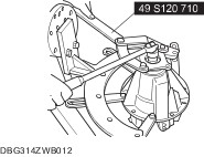
Place a mark on one of the bearing caps so that the left and right bearing caps won’t get mixed up. Use the mark for matching at the time of assembly. | Item 9 : Locknut | | -
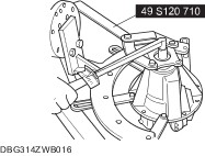
Hold the companion flange using the SST and remove the locknut. | Item 11 : Companion flange | | -
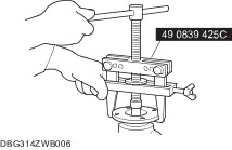
Pull the companion flange out using the SST. | Item 12 : Oil seal | | -
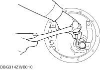
Remove the oil seal using a screw driver. | Item 13 : Drive pinion | | -
Remove the drive pinion by tapping with a plastic hammer. | Item 16 : Rear bearing inner race | | -
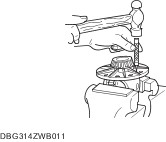
NOTE:Mark or otherwise distinguish between the front and rear inner races so that they are not mixed at the time of reassembly. Remove the rear bearing inner race using the SST. | Item 18 : Front bearing inner race | | -
NOTE:Mark or otherwise distinguish between the front and rear outer races so that they are not mixed up at the time of reassembly. Remove the bearing outer race by using the two grooves on the carrier and tapping the outer races alternately. | Item 19 : Rear bearing outer race | | -
NOTE:Mark or otherwise distinguish between the front and rear outer races so that they are not mixed up at the time of reassembly. Remove the bearing outer race by using the two grooves on the carrier and tapping the outer races alternately. | Item 23 : Knock pin | | -
CAUTION:Insert the bar from the knock pin hole at the opposite side from where the ring gear is installed. Secure the gear case in a vise and remove the knock pin using a 4 mm {0.16 in} diameter bar. | Item 29 : Side bearing inner race | | -
CAUTION:Mark the left bearing in order to install in the same position. Remove the side bearing inner race from the gear case using the SST. | Assembly Details Item 7 : Knock pin | | -
Assemble the side gears, thrust washer, pinion gears, pinion shaft and knock pin. After assembling the knock pin, make a crimp so that the pin will not come out of the gear case. | Item 8 : Ring gear | | -
Coat the ring gear and gear case facing surfaces with locking agent. | | | -
Install the ring gear and tighten the bolt to the specified torque. - Tightening torque 68.6—83.3 Nm {7.00—8.49 kgf·m, 50.6—61.4 ft·lbf}.
| Item 9 : Side bearing inner race | | -
CAUTION:Bearings should be assembled to the original positions. Press the side gearings into the gear case using the SST. | Item 12 : Front bearing outer race | | -
Press the front bearing outer race into the carrier using the SST and a press. | Item 13 : Rear bearing outer race | | -
Press the rear bearing outer race into the carrier using the SST and a press. | Item 14 : Spacer NOTE:Use the installed spacer when adjusting. NOTE:Be careful to install SSTs in the correct position and facing in the correct direction. | | -
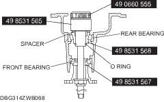
Assemble the spacer, rear bearing inner race, and the SST (49 8531 568) on to the SST (49 8531 565) as shown in the figure. | | | -
Assemble the front bearing inner race, SST (49 8531 567), companion flange, washer and nut to the SST (49 8531 565). | | | -
Tighten the nut to the extent that the SST (49 8531 565) can be turned by hand. | | | -
Place the SST on the surface plate and set the dial gauge to zero. | | | -
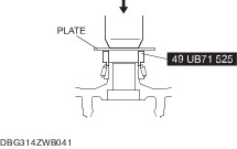
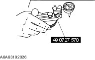
Place the SST (49 0660 555) on top of the SST (49 8531 565), and then set the SST (49 0727 570) on top of the SST (49 0660 555). | | | -
Place the measuring probe of the dial gauge at the point where the side bearing is installed in the differential carrier and measure at the lowest position. Measure the left and right sides. | | | -
NOTE:For example, the measured results obtained step 6 are 0.06 mm {0.0024 in} and 0.04 mm {0.0016 in}, the formula is (0.06+0.04)/2=0.05.Therefore, replace it with a spacer 0.05 mm {0.002 in} thicker than the currently used one. Add the two (left and right) values obtained by the measurements taken in Step 6 and then divide the total by 2. From this sum, subtract the sum of the number inscribed on the end of the drive pinion divided by 100. (If there is no figure inscribed, use 0.) This is the pinion height adjustment value. | Identification mark | Thickness (mm {in}) | Identification mark | Thickness (mm {in}) | | 08 | 3.080 {0.1213} | 29 | 3.290 {0.1295} | | 09 | 3.095 {0.1220} | 30 | 3.305 {0.1301} | | 11 | 3.110 {0.1224} | 32 | 3.320 {0.1307} | | 12 | 3.125 {0.1230} | 33 | 3.335 {0.1313} | | 14 | 3.140 {0.1234} | 35 | 3.350 {0.1319} | | 15 | 3.155 {0.1242} | 36 | 3.365 {0.1325} | | 17 | 3.170 {0.1248} | 38 | 3.380 {0.1331} | | 18 | 3.185 {0.1254} | 39 | 3.395 {0.1337} | | 20 | 3.200 {0.1260} | 41 | 3.410 {0.1343} | | 21 | 3.215 {0.1266} | 42 | 3.425 {0.1348} | | 23 | 3.230 {0.1271} | 44 | 3.440 {0.1354} | | 24 | 3.245 {0.1278} | 45 | 3.455 {0.1360} | | 26 | 3.260 {0.1283} | 47 | 3.470 {0.1366} | | 27 | 3.275 {0.1289} | — | — | | Item 15 : Rear bearing inner race | | -
CAUTION:Press in until the force required suddenly increases. CAUTION:Install the spacer selected for the pinion height adjustment, confirm that the installation direction is correct. Press the rear bearing inner race in using the SSTs. | Item 16 : Drive pinion | | -
CAUTION:Do not install the oil seal. Assemble the following parts to the drive pinion. | | | -
Turn the serrated part of the drive pinion by hand to seat the bearing. | | | -
Tighten the locknut temporarily tightened in Step 1 from the lower limit of the specified tightening torque using the SST, and obtain the specified preload. Record the tightening torque at this time. - Tightening torque128—284 Nm {13.1—28.9 kgf·m, 94.5—209 ft·lbf}.
- Front differential drive pinion preload 1.28—1.76 Nm {13.1—17.9 kgf·cm, 11.4—15.5 in·lbf}.
- If the specified preload cannot be obtained within the specified tightening torque, replace with a new collapsible spacer and adjust again.
| | | -
Remove the locknut, washer, and companion flange. | Item 19 : Oil seal (companion flange) | | -
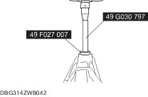
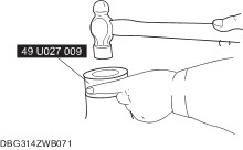
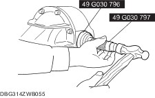
Apply differential oil to the lip of a new oil seal. | | | -
Assemble the oil seal using the SST. | Item 22 : Locknut | | -
Assemble the companion flange and washer. | | | -
Tighten a new locknut using the SST. - Tightening torque128—284 Nm {13.1—28.9 kgf·m, 94.5—209 ft·lbf}.
| Item 23 : Side bearing outer race | | -
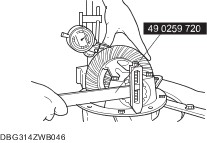
Install the differential gear component to the carrier. After loosely tightening the bearing outer race and bearing cap mounting bolts, completely tighten the adjustment screw by hand. Then, while turning the ring gear, alternately tighten the left and right adjustment screws using the SST. | | | -
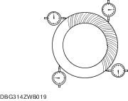
Adjust the drive pinion, ring gear backlash and the side bearing preload as follows: - Mark the ring gear at four points at approx. 90° intervals and mount a dial indicator to the carrier so that the feeler comes in contact at a 90°angle with one of the ring gear teeth.
- Turn both bearing adjusters equally until the backlash becomes 0.09—0.11 mm {0.0035—0.0043 in} using the SST.
| | | -
Inspect for the backlash at the three other marked points and make sure that the minimum backlash is more than 0.05 mm {0.002 in} and difference of the maximum and minimum backlash value is less than 0.07 mm {0.0028 in}. | | | -
After adjusting the backlash, tighten the adjustment screws equally until the distance between both pilot sections on the bearing caps (L) become as specified. - Bearing cap bolt tightening torque73—107 Nm {7.45—10.9 kgf·m, 53.9—78.9 ft·lbf} Distance L 204.5 mm {8.052 in}.
| | | -
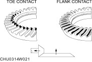
The inspection and adjustment procedure is as follows: - Coat both surfaces of 6—8 teeth of the ring gear uniformly with a tooth marking compound.
- While moving the ring gear back and forth by hand, rotate the drive pinion several times and inspect the tooth contact.
- If the tooth contact is good, wipe off the red lead coating.
- If it is not good, adjust the pinion height, then adjust the backlash.
| | | -
Toe and flank contact. - Replace the spacer with a thinner one, and move the drive pinion outward.
| | | -
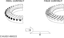
Heel and face contact. - Replace the spacer with a thicker one. Bring the drive pinion inward.
| Item 28 : Oil seal (differential casing) | | -
Tap in the new oil seal to the front differential casing using the SSTs. | |