| Disassembly and Assembly Special Tool(s) | | Clamping Tool, Boot Retaining Clamp 49 T025 001 | CAUTION:Do not damage and remove the dust cover or the ABS sensor rotor on the drive shaft. These parts cannot be purchased separately. Replace the assembled unit if the dust cover or the ABS sensor rotor is damaged and removed. 1. Disassemble the components in the order indicated in the following illustration(s) and table(s). 9 - Shaft and bell joint component 2. To assemble, reverse the disassembly procedure. Disassembly Details Item 1 : Boot band | | -
NOTE:The wheel side boot band does not need to be removed unless replacing it. Pry up the locking clips using a screwdriver. | | | -
Remove the band using pliers. | | | -
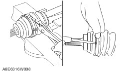
Slide the boot along the shaft to expose the joint. | Item 3 : Outer ring | | -
CAUTION:Mark with paint; do not use a punch. Mark the cage and outer ring for proper assembly. | | | -
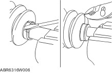
Remove the clip using a screwdriver. | | | -
Remove the outer ring from the inner ring and the balls. | Item 5 : Balls | | -
CAUTION:Mark with paint; do not use a punch. Mark the inner ring and cage. | | | -
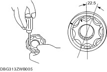
Remove the snap ring using snap-ring pliers. | | | -
Disassemble the balls, inner ring, cage from the drive shaft as component. | | | -
Turn the cage approx. 22.5 degree and pull the cage and balls away from the inner ring. | Item 8 : Boot | | -
NOTE:The wheel side boot does not need to be removed unless replacing it or the bell joint and shaft component. NOTE:Do not strip the tape until the boot is assembled. Wrap the shaft splines with tape. | Assembly Details Item 8 : Boot | | -
CAUTION:Do not touch the grease with your hand. Apply it from the tube to prevent foreign matter from entering the boot. NOTE:The wheel side and differential side boots are different. NOTE:Use the specified grease supplied in the boot kit. Fill the boot (wheel side) with the specified grease from a tube, not by hand. - Graese amount 110-130 g {3.88-4.58 oz}.
| | | -
With the splines of the shaft still wrapped in tape from disassembly, install the boot. | Item 7 : Cage | | -
CAUTION:Install the cage with the offset facing the snap ring groove. If incorrectly installed, the drive shaft may become disengaged. Align the marks and install the balls and cage to the inner ring in the direction shown in the figure. | Item 3 : Outer ring | | -
CAUTION:Do not touch the grease with your hand. Apply it from the tube to prevent foreign matter from entering the boot. NOTE:Use the specified grease supplied in the boot kit. Fill the outer ring and boot with the specified grease. - Graese amount 115-135 g {4.06-4.76 oz}.
| | | -
Align the marks, and install the outer ring on to the shaft. | | | -
Set the drive shaft to the standard length. - Front drive shaft standard length LH: 507.8—517.8 mm {20.00—20.38 in} RH: 596.7—606.7 mm {23.50—23.88 in}.
| | | -
CAUTION:Be careful not to allow the grease to leak. CAUTION:Do not damage the boot. Release any trapped air from the boots by carefully lifting up the small end of each boot with a cloth wrapped screwdriver. | | | -
Verify that the drive shaft length is within the specification. | Item 1 : Boot band | | -
CAUTION:Install the band into the groove securely. Differential side boot. | | -
Fold the band in the direction opposite to the forward revolving direction of the drive shaft and use pliers to pull it tight. | | -
Lock the end of the band by bending the locking clips. | | | -
Wheel side boot. | | -
Adjust clearance A by turning the adjusting bolt of the SST. - Clearance A 2.9 mm {0.11 in}.
| | | -
Crimp the wheel side small boot band using the SST. Verify that clearance B is within the specification. - If clearance B is more than the specification, reduce clearance A of the SST and crimp the boot again.
- If clearance B is less than the specification, replace the boot band, increase clearance A of the SST, and crimp the new boot.
- Clearance B 2.4—2.8 mm {0.095—0.110 in}.
| | | -
Verify that the boot band does not protrude from the boot band installation area. - If it does, replace the boot band and repeat Steps 2 and 3.
| | | -
Fill the boot with the repair kit grease. | | | -
Adjust clearance A by turning the adjusting bolt of the SST. - Clearance A 3.2 mm {0.13 in}.
| | | -
Crimp the wheel side big boot band using the SST. | | | -
Verify that clearance B is within the specification. - If clearance B is more than the specification, reduce clearance A of the SST and crimp the boot again.
- If clearance B is less than the specification, replace the boot band, increase clearance A of the SST and crimp the new boot.
- Clearance B 2.4—2.8 mm {0.095—0.110 in}.
| | | -
Verify that the boot band does not protrude from the boot band installation area. - If it does, replace the boot band and repeat Steps 7 and 8.
| |