| Removal and Installation CAUTION:Performing the following procedures without first removing the ABS wheel-speed sensor may possibly cause an open circuit in the harness if it is pulled by mistake. Before performing the following procedures, remove the ABS wheel-speed sensor (axle side) and fix it to an appropriate place where the sensor will not be pulled by mistake while servicing the vehicle. | | -
If removing the RH drive shaft, drain the front differential oil. | 2. Remove the components in the order indicated in the following illustration(s) and table(s). 3. To install, reverse the removal procedure. Removal Details Item 1 : Wheel hub, steering knuckle | | -
For additional information, refer to: (204-01 Front Suspension) Wheel Knuckle - 4x2 (Removal and Installation), Wheel Knuckle (Removal and Installation), Wheel Knuckle - 4x4 (Removal and Installation). | Item 2 : Drive shaft | | -
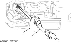
CAUTION:Do not damage the dust cover or the ABS sensor rotor on the drive shaft. These parts cannot be purchased separately. Replace the assembled unit if the dust cover or the ABS sensor rotor is damaged. CAUTION:The sharp edges of the drive shaft can slice or puncture the oil seal. Be careful when removing the drive shaft from the front differential. Remove the drive shaft by prying with a bar inserted between the differential casing and the drive shaft, as shown in the figure. | Installation Details Item 2 : Drive shaft CAUTION:The sharp edges of the drive shaft can slice or puncture the oil seal. Be careful when installing the drive shaft to the front differential. CAUTION:The oil seals are damaged easily if this procedure is not done correctly. | | -
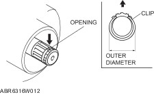
Install a new clip onto the left-hand output shaft with the opening facing upward. Ensure that the diameter of the clip does not exceed the specification for installation. | | | -
After installation, measure the outer diameter. - If it exceeds the specification, repeat Steps 1—2 using a new clip.
- Outer diameter specification 31.2 mm {1.23 in}.
| | | -
Apply differential oil to the oil seal lip. | | | -
Insert the left-hand drive shaft into the output shaft. | | | -
Install a new clip onto the right-hand drive shaft with the opening of a new clip facing upward. | | | -
After installation, measure the outer diameter. - If it exceeds the specification, repeat Steps 1—2 using a new clip.
- Outer diameter specification 33.2 mm {1.31 in}.
| | | -
Install the right-hand drive shaft into the front differential. | | | -
Push the drive shaft into the wheel hub. | | | -
After installation, pull the output shaft side outer ring forward to confirm that the drive shaft is securely held by the clip. | |