| Removal and Installation Special Tool(s) | | Flare Nut Wrench 49 0259 770B | CAUTION:The internal parts of the ABS HU/CM could be damaged if dropped. Be careful not to drop the ABS HU/CM. Replace the ABS HU/CM if it is subjected to an impact. 1. Remove the components in the order indicated in the following illustration(s) and table(s). 7 - Bushing (ABS HU/CM side) 2. To install, reverse the removal procedure. | | -
Bleed the brake system.
For additional information, refer to: Brake System Bleeding (206-00 Brake System - General Information, General Procedures).
| Removal Details Item 1 : Connector | | -
Rotate the lock lever in the direction of the arrow, and remove the ABS HU/CM connector. | Item 2 : Brake pipe | | -
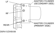
Place an alignment mark on the brake pipe and ABS HU/CM. | | | -
Apply protective tape to the connector to prevent brake fluid from entering. | Installation Details Item 2 : Brake pipe | | -
When installing the brake pipe, align the marks made before removal with the ABS HU/CM as shown in the figure. | | | -
Tighten the brake pipe to the specified torque using the SST (49 0259 770B). | Item 1 : Connector | | -
After connecting the connector, rotate the lock lever in the direction of the arrow to install the ABS HU/CM connector. | |