| Disassembly and Assembly Special Tool(s) | | Power Steering Pump Hanger 49 F032 301 | 1. Disassemble the components in the order indicated in the following illustration(s) and table(s). 2. To assemble, reverse the disassembly procedure. | | -
After installing the P/S pump, flush the power steering system according to the following procedures. - Add ATF until it reaches the MAX level of the P/S fluid tank.
- Start the engine and turn the steering wheel fully to the left and right several times to circulate the ATF.
- If the fluid level is dropped, add ATF
- Drain the ATF.
- Add the new ATF to the MAX level of the P/S fluid tank, and repeat Step (1) and (2) a few times.
| Disassembly Details Item 1 : Stud | | -
Tighten 2 nuts against each other on the stud, and then remove it. | Item 2 : Power steering oil pump component | | -
CAUTION:Use the SST to prevent damage to the pump when securing it in a vise. Secure the power steering oil pump using the SST. | Item 17 : Gear shaft component | | -
Remove the snap ring to front body shown in the figure. | | | -
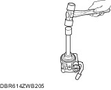
Tap the gear shaft from the shaft side using a plastic hammer to remove it. | Item 18 : Oil seal | | -
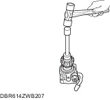
CAUTION:To prevent damaging the power steering oil pump body when tapping it out, wrap a clean rag on the end of the flathead screwdriver. If the power steering oil pump body is damaged, replace it together with the power steering oil pump component. Tap the oil seal out using a flathead screwdriver. | Assembly Details Item 18 : Oil seal | | -
CAUTION:Install it so that the side with narrow groove points outwards. Press fit the oil seal using a proper pipe. | Item 17 : Gear shaft component | | -
Set a proper pipe into the gear depression and press fit the gear shaft. | | | -
Install the snap ring to front body shown in the figure. | Item 14 : Side plate | | -
Install the side plate in the front pump body shown in the figure. | Item 13 : Vane | | -
Install the rotor in the front pump body shown in the figure. | | | -
Install the cam ring in the front pump body shown in the figure. | | | -
Install the vane in the rotor. | Item 9 : Rear pump body | | -
Install a new O-ring and the side plate to the front body. | | | -
Position the side plate using the rear pump body. | | | -
Install the rear body to the rear pump body. | Item 1 : Stud | | -
Tighten 2 nuts against each other on the stud, and then install it so that the stud projection is within specification shown in illustration. | |