| Assembly Special Tool(s) | | Valve Guide Installer 49 0221 251A | | | Piston Pin Installer 49 0636 040 | | | Main Bearing Puller & Installer 49 0813 235 | | | Attachment A 49 B032 308 | | | Attachment A 49 D032 326A | | | Wrench 49 F017 1A0 | | | Support 49 G028 203 | | | Handle 49 G030 797 | | | Handle 49 G033 102 | | | Installer 49 H025 001 | | | Socket 49 UN01 011 (308-168) | 1. Assemble the components in the order indicated in the following illustration(s) and table(s). 5 - Countershaft front bearing 6 - Countershaft rear bearing 7 - Maindrive gear bearing race 23 - Synchronizer key spring 43 - Reverse idler gear shaft 69 - Select spindle component 71 - Select lock spindle spring Assembly Details Item 2 : Countershaft component | | -
Install the countershaft component. | | -
Install the maindrive gear. | | | -
Install the mainshaft component. | | | -
Assemble the Mainshaft component and Maindrive gear. | | | -
Install the countershaft front and rear bearing. | | | -
Install the maindrive gear bearing race and mainshaft center bearing race. | | | -
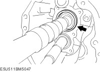
Install the bearing cover with the arrow pointing to the top of the case. - Tightening torque: 17.7—26.4 Nm {1.81—2.69 kgf·m, 13.1—19.4 ft·lbf}.
| | | -
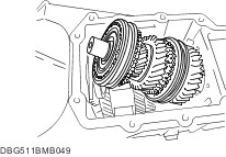
Select the mainshaft component and countershaft component bearing shims according to the following procedure. CAUTION:Securely assemble the mainshaft, maindrive gear component, and countershaft component so that there is no looseness or play. - Set the clutch housing side upward and level the transmission case.
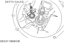
- Using a depth gauge, measure the maindrive gear bearing outer race height A.
| | | -
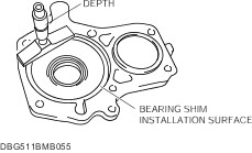
Using a depth gage, measure the maindrive gear bearing retainer depth B. | | | -
Calculate and select the correct maindrive gear bearing shim thickness. - C: Dimension between the maindrive gear bearing and bore in the front cover.
- B: Depth of the maindrive gear bearing bore in the front cover.
- A: Maindrive gear bearing height.
- Maindrive gear shaft total end play 0.05—0.15 mm {0.002—0.0059 in}.
| | | -
NOTE:The countershaft bearing is located below the contact surface of the case and front cover. Using a depth gauge, measure the countershaft front bearing depth D. | | | -
Using a depth gauge, measure the countershaft front bearing retainer depth E. | | | -
Calculate and select the correct countershaft front bearing shim thickness. - F: Dimension between the countershaft front bearing and bore in the front cover.
- E: Depth of the countershaft front bearing bore in the front cover.
- D: Countershaft front bearing depth.
- Countershaft total end play 0.15—0.25 mm {0.006—0.0098 in}.
| Item 10 : Front oil seal | | -
Apply specified grease to the lip of a new oil seal. | | -
Install the oil seal to the front cover using the SST. | Item 11 : Bearing shim | | -
NOTE:If necessary, apply a light coat of petroleum jelly to the shims and oil baffle. Position the maindrive gear bearing shim, oil baffle, and the countershaft bearing shim onto the front cover. | Item 14 : Pivot pin | | -
Install the pivot pin. - Tightening torque: 31—46 Nm {3.2—4.6 kgf·m, 23—33 ft·lbf}.
| Item 15 : Front cover | | -
Apply sealant to the contact surfaces of the transmission case and front cover as shown in the figure. | | | -
Install the pivot pin. - Tightening torque: 31—46 Nm {3.2—4.6 kgf·m, 23—33 ft·lbf}.
| | | -
NOTE:To prevent damage to the oil seal lip during assembly, tape maindrive gear shaft splines. Install the front cover to the transmission case. - Tightening torque: 19—25 Nm {2.0—2.5 kgf·m, 15—18 ft·lbf}.
| Item 18 : 5th gear bearing inner race | | -
Install the steel ball to the countershaft. | | -
Align the ball groove position of the 5rd gear bearing inner race and assemble it to the countershaft. | Item 30 : 5th/reverse clutch hub and shift fork component | | -
CAUTION:Be sure to assemble the clutch hub components and synchronizer ring components while aligning the synchronizer ring grooves with the synchronizer keys. Assemble the 5th drive gear and 5th/reverse clutch hub component. | | -
The standard synchronizer key dimensions are as follows: | mm {in} | A | B | C | | 5th/6th | 18.0 {0.709} | 5.45 {0.215} | 6.0 {0.236} | | | | -
Align the clutch hub sleeve alignment mark with the clutch hub synchronizer key installation position and assemble. | | | -
Install the 5th/reverse shift rod retaining bolt. - Tightening torque: 21.6—30.4 N·m {2.21—3.09 kgf·m, 16.0—22.4 ft·lbf}
| | -
Install the thrust washer. | | | -
Measure the clearance between thrust washer and groove of the countershaft. If not within the specification, adjust by choosing the proper thrust washer. - 5th/Reverse clutch hub end play 0—0.05 mm {0.0—0.0019 in}
| | -
5th/Reverse clutch hub thrust washer thickness (mm {in}) - 3.00 {0.118}
- 3.05 {0.120}
- 3.10 {0.122}
- 3.15 {0.124}
- 3.20 {0.126}
- 3.25 {0.128}
- 3.30 {0.130}
- 3.35 {0.132}
- 3.40 {0.134}
| Item 32 : Counter lever shaft component | | -
CAUTION:If the counter lever shaft has been replaced or the locknut is loose, assemble the counter lever shaft with the chamfer side of the shaft pointed straight upward. CAUTION:Apply sealant to the threads of the locknut. Install the counter lever shaft component. | | -
If there is an abnormality in the 3rd/4th shift stroke after assembling, loosen the locknut and readjust. | Item 41 : Reverse gear | | -
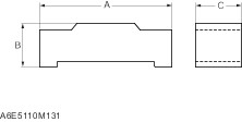
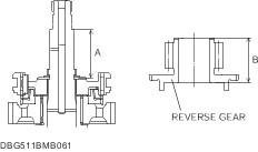
Measure the clearance A and B. | | | -
Calculate and select the thrust washer thickness. | Formula: C = A - B | | C: Dimension between the 5th/Reverse clutch hub and reverse gear | | B: Reverse gear height | | A: Dimension between the 5th/Reverse clutch hub and thrust washer | - Refer to the reverse gear thrust washer selective chart.
Reverse gear thrust washer | Dimension C (mm {in}) | Thickness (mm {in}) | | 7.60—7.70{0.300—0.303} | 7.35 {0.289} | | 7.70—7.80{0.304—0.307} | 7.45 {0.293} | | 7.80—7.90{0.308—0.311} | 7.55 {0.297} | | 7.90—8.00{0.312—0.314} | 7.65 {0.301} | | 8.00—8.10{0.315—0.318} | 7.75 {0.305} | - Reverse gear end play0.25—0.35 mm {0.002—0.0059 in}
| | | -
Install the thrust washer. | | | -
Install the reverse gear. | Item 49 : Reverse idler gear shaft component | | -
Using the SSTs, install the friction damper to the reverse idler gear. | | | -
Verify the depth of the friction damper installation position. | | | -
Assemble the reverse idler gear component. | | | -
Measure the clearance between the retaining ring and thrust washer. If not within the specification, adjust by choosing the proper retaining ring. - Reverse idler gear end play0.1—0.2 mm {0.0040—0.0078 in}
| | -
Reverse idler gear retaining ring thickness (mm {in}) - 1.5 {0.059}
- 1.6 {0.063}
- 1.7 {0.067}
- 1.8 {0.071}
- 1.9{0.075}
| | | -
Install the reverse idler gear component to the transmission case. | | | -
Install the reverse idler gear shaft retaining bolt. - Tightening torque78.5—117 N·m {8.01—11.9 kgf·m, 57.9—86.2 ft·lbf}
| Item 53 : Mainshaft rear bearing | | -
Slide the 3rd/4th and 1st/2nd clutch hub sleeves to lock the transmission into 4th and 2nd gears. | | -
Insert the mainshaft rear bearing into the mainshaft and install the locknut. | Item 54 : Locknut | | -
CAUTION:Attach the SST with the locknut seated in the bearing. Attach the SST to the locknut and tighten the nut to the specified torque. - Tightening torque: 211—269 N·m {21.6—27.4 kgf·m, 156—198 ft·lbf}
| Item 56 : Countershaft rear bearing | | -
Tighten the countershaft locknut in the counterclockwise direction. - Tightening torque: 127—196 N·m {13.0—19.9 kgf·m, 94—144 ft·lbf}
| | | -
Using the pin punch, stake the mainshaft rear bearing locknut. | Item 57 : Locknut | | -
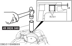
Using the pin punch, stake the countershaft rear bearing locknut. | Item 61 : Bush | | -
Install the bush using the SST. - Installation depth A: 1—2 mm {0.040—0.078 in}.
| | | -
Install the bush using the suitable steel bar through the sealing cap hole as shown in the figure. - Distance A: Approx. 200 mm {7.87 in}.
- Distance B: Approx. 17.0—17.5 mm {0.670—0.688 in}.
- Installation depth C: 1—2 mm {0.040—0.078 in}.
| Item 62 : Oil seal (control rod) | | -
Apply specified grease to the lip of a new oil seal. | | -
Install the oil seal using the SSTs through the sealing cap hole as shown in the figure. - Installation depth A: 109.5—110.5 mm {4.312—4.350 in}.
| Item 63 : Sealing cap | | -
CAUTION:Apply silicone sealant to the sealing cap. Install the sealing cap using the SSTs. - Installation depth A: 0.5—2.0 mm {0.020—0.078 in}.
| Item 67 : Extension housing | | -
Apply sealant to the contact surfaces of the extension housing and transmission case as shown in the figure. | | -
Install the extension housing to the transmission case. - Tightening torque: 31.4—46.0 Nm {3.21—4.69 kgf·m, 23.2—33.9 ft·lbf}.
| Item 73 : Oil seal (extension housing) | | -
Apply specified grease to the lip of a new oil seal. | | -
Install the oil seal evenly and gradually using the SST and a hammer. | Item 76 : Top cover, shift component | | -
Apply sealant to the contact surfaces of the transmission case and top cover as shown in the figure. | | -
Install the top cover component to the transmission case. - Tightening torque: 15.7—22.5 Nm {1.60—2.29 kgf·m, 11.6—16.5 ft·lbf}.
| Item 77 : Blind cover | | -
Apply sealant to the contact surfaces of the blind cover and extension housing as shown in the figure. | | -
Install the blind cover to the extension housing. - Tightening torque: 7.9—9.8 Nm {81—99 kgf·cm, 70—86 in·lbf}.
| Item 78 : Control case | | -
Apply sealant to the contact surfaces of the control case and extension housing as shown in the figure. | | -
Install the control case to the extension housing. - Tightening torque: 15.7—22.5 Nm {1.60—2.29 kgf·m, 11.6—16.5 ft·lbf}.
| Item 89 : Release fork | | -
Apply specified grease to the areas shown in the figure. | | -
Install the release collar and release fork. | |