| Disassembly Special Tool(s) | | Piston Pin Installer 49 0636 040 | | | Bearing Puller Set 49 0839 425C | | | Attachment A 49 B032 308 | | | Wrench 49 F017 1A0 | | | Handle 49 G033 102 | | | Hook 49 H017 101 | | | Socket 49 UN01 011 | CAUTION:Remove the oil seal (extension housing and control rod) only if there is a malfunction. 1. Disassemble the components in the order indicated in the following illustration(s) and table(s). 19 - Select spindle component 21 - Select lock spindle spring 35 - Countershaft rear bearing 48 - Reverse idler gear shaft 68 - Synchronizer key spring 73 - 5th gear bearing inner race 82 - Maindrive gear bearing race 84 - Countershaft front bearing 85 - Countershaft rear bearing Disassembly Details Item 4 : Top cover, shift component | | -
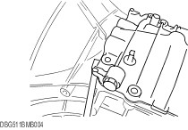
Pry the seal open at the projection on the case using a flathead screwdriver or similar tool as shown in the figure, and then remove the top cover. | Item 23 : Oil seal (extension housing) | | -
Remove the oil seal using a flathead screwdriver as shown in the figure. | Item 24 : Extension housing | | -
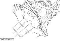
NOTE:Pry open the seal at the projection on the case using a flathead screwdriver or similar tool as shown in the figure, and then remove the extension housing. Remove the extension housing component. | Item 28 : Oil seal (control rod) | | -
Using a flathead screwdriver, remove the oil seal as shown in the figure. | Item 29 : Bush | | -
Remove the bush using the SST. | | | -
Remove the bush using the suitable steel bar through the sealing cap hole as shown in the figure. - Distance A: Approx. 200 mm {7.87 in}
- Distance B: Approx. 17.0—17.5 mm {0.670—0.688 in}
| Item 30 : Sealing cap | | -
CAUTION:Remove the sealing cap only if there is malfunction. Remove the sealing cap using the SST. | Item 34 : Locknut | | -
Slide the 3rd/4th and 1st/2nd clutch hub sleeves to lock the transmission into 4th and 2nd gears. | | | -
Remove the countershaft rear bearing locknut by rotating it clockwise. | | | -
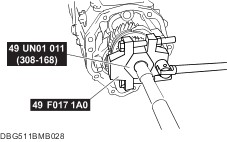
Remove the mainshaft rear bearing locknut by rotating it counterclockwise using the SST. | Item 37 : Locknut | | -
Slide the 3rd/4th and 1st/2nd clutch hub sleeves to lock the transmission into 4th and 2nd gears. | | | -
Remove the countershaft rear bearing locknut by rotating it clockwise. | | | -
Remove the mainshaft rear bearing locknut by rotating it counterclockwise using the SST. | Item 38 : Mainshaft rear bearing | | -
Using the SSTs remove the mainshaft rear bearing. | Item 42 : Reverse idler gear shaft component | | -
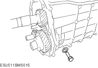
Remove the reverse idler gear shaft retaining bolt and then remove the reverse idler gear shaft component from the transmission case. | Item 49 : Friction damper | | -
Remove the friction damper using a flathead screwdriver. | Item 57 : Counter lever | | -
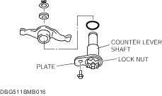
CAUTION:To prevent the shaft position from deviating when removing the counter lever, remove the countershaft lever component without loosening the locknut unless it is necessary. | Item 59 : Counter lever shaft component | | -
CAUTION:To prevent the shaft position from deviating when removing the counter lever, remove the countershaft lever component without loosening the locknut unless it is necessary. | Item 61 : 5th/reverse clutch hub and shift fork component | | -
Remove the 5th/reverse shift rod retaining bolt. | | | -
Remove the 5th/reverse shift fork component and 5th/reverse clutch hub component at the same time. | Item 77 : Front cover | | -
CAUTION:Insert the front cover tightening bolts into the bolt holes for the front cover disassembly, tighten the two bolts uniformly and, then remove the front cover. Remove the front cover. | Item 83 : Mainshaft bearing race | | -
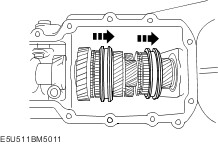
Grasping the mainshaft and countershaft, move them forward and back to remove the bearing races. | Item 86 : Mainshaft component | | -
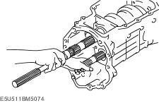
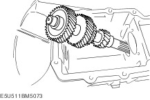
Tilt the mainshaft component as shown in the figure and remove it from the transmission case. | | -
Remove the maindrive gear. | | | -
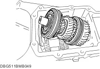
Tilt the countershaft component as shown in the figure and remove it from the transmission case. | |