| Disassembly and Assembly Special Tool(s) | | Snap ring pliersadapter 307-605 | | | Drift bush input shaft 307-606 | | | Drift NRB input shaft 307-607 | | | Drift ball bearing input shaft 307-608 | | | Drift NRB fitting cover 307-609 | | | Drift ball bearing 307-610 | | | Repair fixture 307-611 | | | Seal driver 307-612 | | | Flange holder rear 307-613 | | | Flange holder front 307-614 | | | Dust deflector press tool 307-615 | | | -
NOTE:Always replace the hose coupling, O-ring and oil seal with new parts. Visually check all the parts for damage. Referring to normal gear tooth face, specifically inspect the uneven wear and chips of gear tooth, replace if necessary. | | | -
NOTE:Before cleaning, check the magnet for the presence of metal particles which indicate internal chipping of the transfer case. Using a cleaning solvent, clean the old oil and dirt deposits. After cleaning dry the parts with low pressure (138 kPa {1.41 kgf/cm2, 20 psi maximum}) compressed air. Lubricate the ball bearings and needle bearing with oil. Protect lubricated bearings from dust. | Disassembly 6 - Center transfer case component 10 - Front transfer case component 18 - Planetary gear component 24 - Reduction shift fork component 26 - Reduction shift fork facing 27 - Lockup shift fork component 29 - Lockup shift fork facing 36 - Output shaft and gerotor pump component 55 - Front output flange component 61 - Rear transfer case component 76 - Rear companion flange component | | -
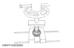
Using the SST, set the transfer case as shown in the figure. | | | -
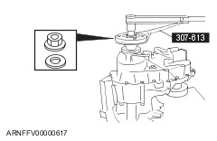
Secure the rear companion flange component using the SST. | | -
Remove the nut and washer. | | | -
Remove the rear companion flange using the pulley. | | | -
Remove the deflector from the flange. | | | -
Remove the oil seal from the output shaft. | | | -
Remove the bracket and speed sensor. | | | -
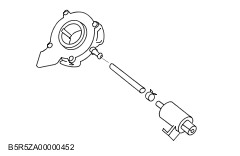
Remove the motor component. | | | -
Remove the clutch coil terminal from the connector and pull out the wiring harness from the sleeve. | | | -
Remove the two oil plugs from the rear transfer case. | | | -
Remove the 14 bolts, identification tag and bracket. | | | -
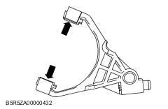
CAUTION:When prying at the transfer case, be careful not to damage the case. Pry at the transfer case projection as shown in the figure a flathead screwdriver, and remove the rear transfer case from the center transfer case. | | | -
Remove the spacer. | | -
Using a flathead screwdriver, remove the oil seal. | | | -
Remove the snap ring. | | -
Pull out the ball bearing from the rear transfer | | | -
Pull out the needle bearing from the rear transfer case. | | | -
Remove the return spring. | | | -
Remove the 3 nuts. | | -
Remove the clutch coil from the rear transfer case. | | | -
CAUTION:Be careful not to damage the metal surface. Remove the snubber from the rear transfer case. | | -
Clean and remove the sealant of the rear transfer case and center transfer case. | | | -
Remove the clutch housing from the output shaft. | | | -
Slide the lockup component and the lockup shift fork component as a single unit to remove the lockup component from the output shaft. | | -
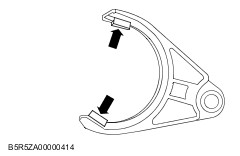
Remove the lockup shift fork component from the lockup component. | | | -
Remove the two fork facings from the lockup shift fork. | | | -
Remove the snap ring, lockup hub and return spring from the lockup collar. | | | -
Remove the snap ring and spacer from the output shaft. | | | -
Remove the drive chain, driven sprocket and drive sprocket from the output shaft at a time. | | -
Separate the drive chain and sprockets. | | | -
Remove the magnet from the slot in the center transfer case. | | -
Remove the strainer from the center transfer case. | | | -
Remove the output shaft component and gerotor pump component from the center transfer case. | | | -
Remove the gerotor pump component from the output shaft. | | -
Loosen the hose clamp and remove the pump hose from the gerotor pump component. | | | -
Remove the hose clamp, pump hose and strainer. | | | -
Remove the reduction hub, reduction shift fork component, rail shaft and shift shaft component from the center transfer case. | | | -
Remove the two shift fork facings from the reduction shift fork component. | | | -
Disassemble the cam, spring, spacer, and shift shaft. | | | -
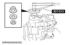
Secure the flange using the SST. | | -
Remove the nut and washer. | | | -
Remove the deflector from the flange. | | -
Pull out the front output flange component. | | -
Remove the lower output shaft. | | | -
Remove the oil seal from the lower output shaft. | | -
Remove the deflector from the flange only when replacement is necessary. | | | -
Remove the breather pipe. | | | -
Remove the front transfer case six bolts. | | -
CAUTION:When prying at the transfer case, be careful not to damage the case. Remove the front transfer case by separating the adapter sealer bond using a flathead screwdriver. | | | -
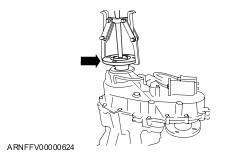
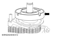
NOTE:Expand the snap ring using the SST, and separate the planetary gear component and the input shaft component from the front transfer case. Remove the input shaft component and planetary gear component from the front transfer case. | | -
Remove the snap ring and oil seal from the front transfer case. | | | -
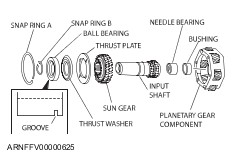
Remove the snap ring A. | | -
Pull out the input shaft component and sun gear from the planetary gear component. | | -
Remove the snap ring B. | | | -
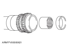
Remove the ball bearing, thrust washer, thrust plate from the input shaft using the press. | | | -
Remove the needle bearing and bushing from the input shaft component. | | | -
Using a flathead screwdriver, remove the oil seal. | | -
Remove the snap ring. | | -
Remove the ball bearing | | | -
NOTE:Do not remove the ring gear from the center transfer case. Remove the dowel pins from the center transfer case. | Assembly 6 - Center transfer case component 10 - Front transfer case component 18 - Planetary gear component 24 - Reduction shift fork component 26 - Reduction shift fork facing 27 - Lockup shift fork component 29 - Lockup shift fork facing 36 - Output shaft and gerotor pump component 55 - Front output flange component 61 - Rear transfer case component 76 - Rear companion flange component | | -
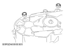
Insert two new dowel pins. | | | -
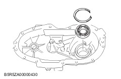
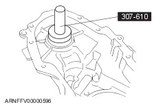
Press the ball bearing into the center transfer case using the SST. | | -
Install the snap ring. | | | -
Install the new oil seal, by pressing it into the center transfer case using the SST. | | | -
Press the new needle bearing into the input shaft using the SST. | | | -
Press the new bushing into the input shaft using the SST. | | | -
Assemble the sun gear and thrust plate to the input shaft. | | | -
Assemble the thrust washer and ball bearing to the input shaft using the SST. | | -
Install the snap ring B. | | | -
NOTE:Verify that the retaining ring is assembled to the upper groove of the planetary gear component on the workbench. Assemble the planetary gear component to the planet carrier as shown in the figure. | | -
Install the snap ring A to the planetary gear component. | | | -
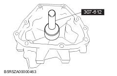
Press the new oil seal into the front transfer case using the SST. | | | -
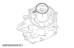
Install the snap ring by making sure that the snap ring is correctly installed into the groove. | | | -
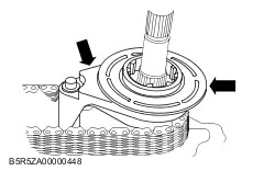
Place the input shaft component onto the front transfer case and assemble the planetary gear component to the groove while expanding the ends of the snap ring using the SST. | | | -
Apply sealant to the front transfer case as shown in the figure. | | | -
Install the front transfer case on the center transfer case. | | -
Install the six bolts and clip. - Tightening torque 34—41 N·m {3.5—4.1 kgf·m, 26—30 ft·lbf}
| | | -
Install the breather pipe on the center transfer case. - Tightening torque 4—7 N·m {41—71 kgf·cm, 36—61 in·lbf}
| | | -
Press in the new deflector to the flange using the SST. | | | -
Assemble the lower output shaft to the center transfer case. | | -
Assemble the front output flange component, oil seal washer, and nut. | | -
Secure the flange using the SST. | | -
Tighten the nut. - Tightening torque 305—332 N·m {31.2—33.8 kgf·m, 225—244 ft·lbf}
| | | -
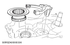
Install the two fork facings on the reduction shift fork component. | | | -
Install the reduction hub to the shift fork. | | -
Install the reduction hub and shift fork component to the planetary gear component. | | | -
Insert the spacer torsion spring and cam into the shift shaft. | | | -
Press them in until area A of the cam contacts area B of the torsion spring, and area C of the torsion spring contacts area D of the shift shaft. | | | -
Rotate the cam to the position indicated in the figure, and press it to the shift shaft side until it contacts the torsion spring. | | | -
Install the cam component in the case as shown in the picture. | | -
Verify that the reduction fork roller is seated in the cam groove as shown in the figure. | | -
Assemble the rail shift to the reduction fork bore. | | | -
Using a hose clamp, tighten the pump hose at the end where it is coupled with the strainer. | | | -
Align the gerotor pump rotor slot and the pump body slot so that they are in a single line. | | | -
Slide the gerotor pump component on the output shaft over pump pin. | | | -
Assemble the output shaft from the center transfer case. | | -
Assemble the output shaft spline to the reduction hub. | | -
Engage the output shaft end with the input shaft bearing. | | | -
Couple the strainer with the case and insert the magnet into the transfer case slot. | | -
Assemble the drive sprocket to the output shaft. | | -
Assemble the lower output shaft to the driven sprocket. | | | -
Install the drive chain onto the sprockets. | | -
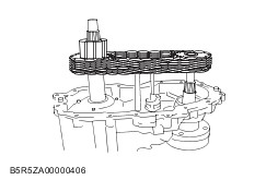
While keeping the tension of the drive chain, assemble the transfer case and drive chain component in parallel. | | -
While rotating the driven sprocket, engage it with the front output shaft spline. | | | -
Assemble the spacer to the front output shaft. | | -
Assemble the snap ring into the groove. | | | -
Install the lockup hub and return spring to the lock up collar and insert the snap ring. | | | -
Install the two new facings to the fork. | | | -
Assemble the lockup component to the lockup fork and assemble them to the drive shaft and the rail shaft. | | | -
Install the clutch housing on the output shaft. | | | -
Position the end of the new needle bearing with the identification mark facing upwards and press it into the cover using the SST. | | | -
Press the ball bearing into the rear transfer case using the SST and install the snap ring. | | | -
Install the coil inside the rear transfer case. | | -
Install the three nuts. - Tightening torque 8—11 N·m {82—112 kgf·cm, 71—97 in·lbf}
| | | -
Install the snubber. - Tightening torque 8—11 N·m {82—112 kgf·cm, 71—97 in·lbf}
| | -
Install the return spring over rail shaft in the rear transfer case. | | | -
Apply a 1.6 mm {0.063 in} bead of sealant to the transfer case mounting surface, and assemble the cover and the transfer case. | | | -
CAUTION:Do not use excessive force. NOTE:For installation of cover, align the cover with transfer case. Install the rear transfer case onto the center transfer case as follows. - Align the cover holes with the transfer case dowel pins.
- Align the cover bearings with output shafts.
- Align the shift shaft with cover boss.
- Align the cover blind hole with rail shaft and make sure that return spring is not cocked.
| | | -
Install the 14 bolts, identification tag and bracket. | | | -
Install the new oil seal. | | | -
Align the motor component with the shift shaft and assemble it to the rear transfer case. | | -
Rotate the motor in clockwise direction to check correct engagement. | | | -
Install the speed sensor in the rear transfer case. | | -
Install the bracket and bolts to the motor component. - Tightening torque 8—11 N·m {82—112 kgf·cm, 71—97 in·lbf}
| | | -
Pass the clutch coil wiring harness through the sensor harness sleeve, and connect the coil terminal to the connector. | | -
Install the motor connector and sensor connector to the motor bracket. | | | -
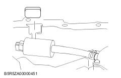
Bundle the wiring harness between the speedometer component and terminal connector using a wiring harness protector and tie wraps. | | -
Install the oil plug to the rear transfer case. - Tightening torque 19—30 N·m {2.0—3.0 kgf·m, 15—22 ft·lbf}
| | | -
Install the spacer over output shaft spline. | | | -
Press the new oil seal into the rear transfer case component using the SST. | | | -
Press in the new deflector to the flange using the SST. | | | -
Install the rear companion flange component, oil seal, washer and nut. | | -
Holding the rear companion flange using the SST, tighten the nut. - Tightening torque 305—332 N·m {31.2—33.8 kgf·cm, 225—244 in·lbf}
| | |