
Ranger 2WD L4-122 2.0L SOHC (1984)
bushings will not have an arrow and may be turned in either direction as long as the lugs on the yoke engage the slots in the bushing.
5.
Remove and discard lower ball joint stud nut, then install a new nut and torque to 40 ft. lbs.
6.
Install new upper ball joint stud nut and torque to 85-100 ft. lbs. Continue to tighten nut until cotter pin hole lines up with castellation on nut, then
install cotter pin. Retorque lower ball joint stud nut to 95-110 ft. lbs. The camber adjuster will be seated at a predetermined position during
the tightening sequence. Do not attempt to change this position.
7.
Reinstall wheels and lower vehicle.
CASTER ADJUSTMENT
Caster angle is non-adjustable on 4 x 4 vehicles. On 4 x 2 models, a service kit, Part No. E4TA-3K064-AA, is available which can be used to increase
caster up to 3° in {1/2}° increments. The kit comes with complete instructions, and these instructions should be strictly followed to achieve desired
results.
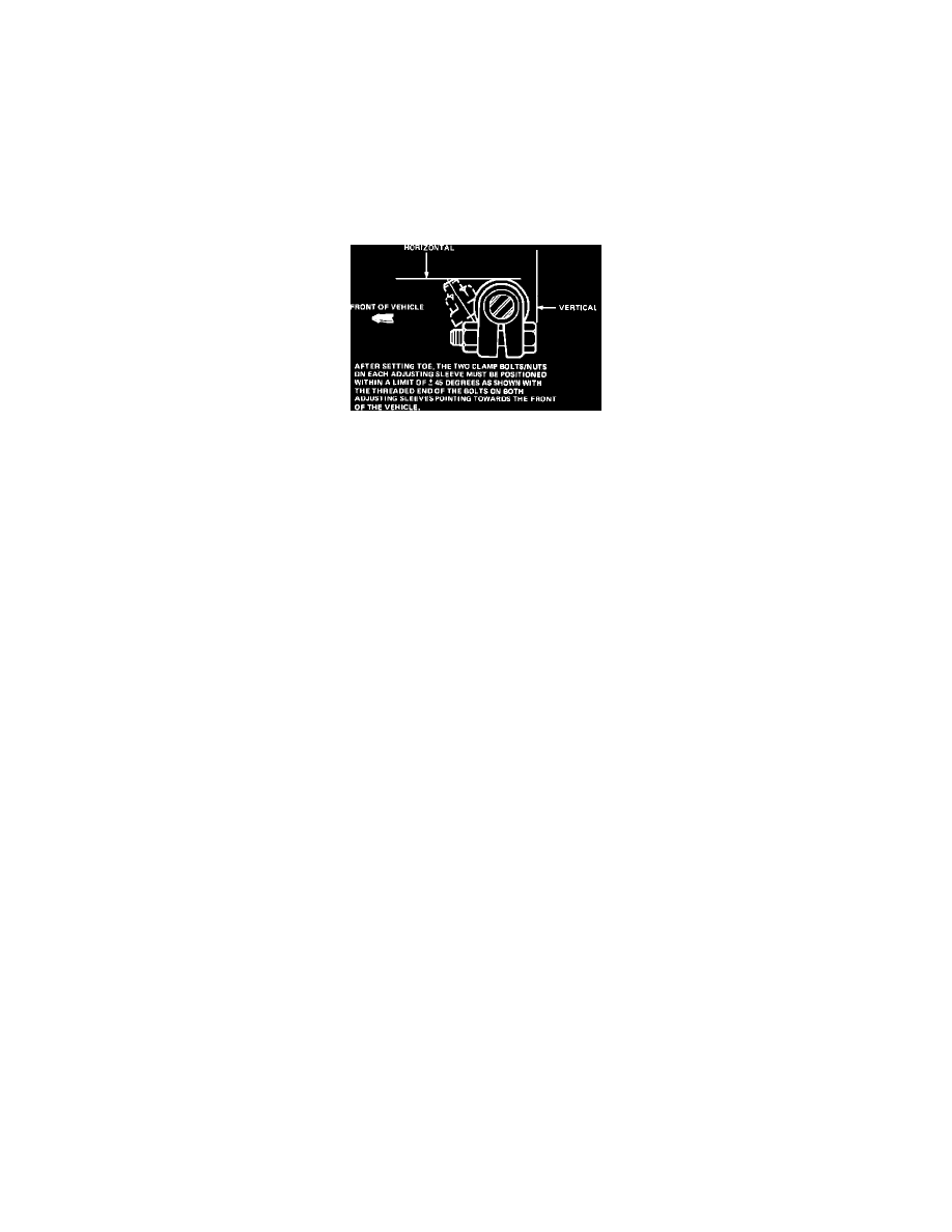
Fig. 4 Toe-In Adjustment
TOE-IN, ADJUST
1.
Loosen clamp bolts at each end of spindle connecting rod tube, then rotate the sleeve until correct toe alignment of {1/32} inch is obtained.
2.
Center clamps between adjustment sleeve nibs, then position bolts horizontally with clamps nuts positioned as shown in Fig. 9.
3.
Recheck toe-in adjustment, then check that steering wheel spokes are properly positioned and adjust as necessary.