
Ranger 2WD L4-153 2.5L SOHC VIN C SFI (1998)
Multifunction Electronic Control Module: Service and Repair
REMOVAL
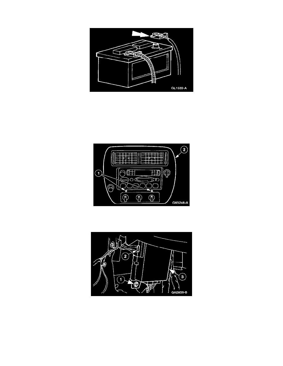
1. Disconnect the battery ground cable.
CAUTION: Electronic modules are sensitive to static electrical charges. If exposed to these charges, damage may result.
NOTE: The Central Timer Module (CTM) must be reconfigured upon replacement. Refer to the New Generation STAR (NGS) Tester help
screen on the configuration card to program the Tire Size, Axle Ratio.
2. Remove the radio chassis.
3. Remove the center instrument panel finish panel.
1
Remove the screws.
2
Remove the center instrument panel finish panel.
4. Remove the Generic Electronic Module (GEM)/Central Timer Module (CTM).
1
Remove the screw.
2
Disconnect the four connectors from the GEM/CTM.
3
Remove the GEM/CTM.
INSTALLATION