
Ranger 2WD L4-153 2.5L SOHC VIN C SFI (1998)
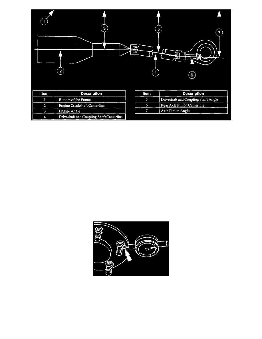
Driveline angularity is the angular relationship between the engine crankshaft, the driveshaft, and the rear axle pinion. Factors determining driveline
angularity include ride height, rear spring, and engine mounts.
An incorrect driveline (pinion) angle can often be detected by the driving condition in which the vibration occurs.
-
A vibration during coastdown from 72 to 56 km/h (45 to 35 mph) is often caused by an excessive U-joint angle at the axle (pinion nose
downward).
-
A vibration during acceleration, from 56 to 72 km/h (35 to 45 mph) may indicate an excessive U-joint angle at the axle (pinion nose upward).
When these conditions exist, check the driveline angles.
If the tires and driveline angle are not the cause, perform the NVH tests to determine whether the concern is caused by a condition in the axle.
UNIVERSAL JOINT (U-JOINT) WEAR
Place the vehicle on a frame hoist and rotate the driveshaft by hand. Check for rough operation or seized U-joints. Replace the U-joint if it shows signs
of seizure, excessive wear, or improper seating.
WHEEL HUB OR AXLE FLANGE BOLT CIRCLE RUNOUT
NOTE: The brake discs/drums must be removed to perform all runout measurements.
1. Position the Dial Indicator with Bracketry perpendicular to the wheel hub or axle flange bolt, as close to the hub or flange face as possible. Zero
the indicator to allow the pointer to deflect either way.
2. Rotate the hub or flange until the next bolt is contacted. Record the measurement and continue until each bolt is checked. The difference between
the maximum and minimum contact readings will be the total wheel hub or axle flange bolt pattern runout. The runout must not exceed 0.38 mm
(0.015 inch).
PILOT RUNOUT