
Ranger 2WD L4-2.3L (2009)
GO to F2.
No
VERIFY the Battery Junction Box (BJB) fuse 27 (20A) and SJB fuses 10 (10A) and 28 (15A) are OK. If OK, REPAIR the circuit in question. If not OK,
REFER to the Wiring Diagrams to identify the possible causes of the circuit short. CLEAR the DTCs. REPEAT the network test with the scan tool.
-------------------------------------------------
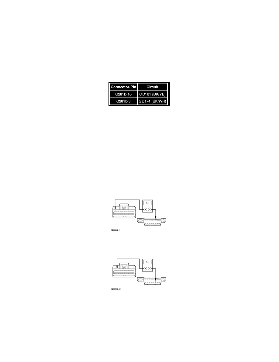
F2 CHECK THE 4X4 CONTROL MODULE GROUND CIRCUITS FOR AN OPEN
-
Ignition OFF.
-
Disconnect: Negative Battery Cable.
-
Measure the resistance between the 4X4 control module, harness side and ground as follows:
-
Are the resistances less than 5 ohms?
Yes
GO to F3.
No
REPAIR the circuit in question. CONNECT the negative battery cable. CLEAR the DTCs. REPEAT the network test with the scan tool.
-------------------------------------------------
F3 CHECK THE HS-CAN CIRCUITS BETWEEN THE DLC AND THE 4X4 CONTROL MODULE FOR AN OPEN
-
Measure the resistance between the 4X4 control module C281a-10, circuit VDB04 (WH/BU), harness side and the Data Link Connector (DLC)
C251-6, circuit VDB04 (WH/BU), harness side.
-
Measure the resistance between the 4X4 control module C281a-9, circuit VDB05 (WH), harness side and the DLC C251-14, circuit VDB05
(WH), harness side.
-
Are the resistances less than 5 ohms?
Yes
CONNECT the negative battery cable. GO to F4.
No
REPAIR the circuit. CONNECT the negative battery cable. CLEAR the DTCs. REPEAT the network test with the scan tool.